Ok, so its been a while (again) you'd think i'd have nothing to do because of the pandemic and I should've had a chance to update earlier. Actually, quite the opposite, i've been super busy. A lot has happened in the world and on my cars since the last one so i'll try and lay it all out as it happened.. at least as far as the cars are concerned.
The splitter mounting was easy enough (says someone who just signed the check, hah). Actually the more and more I do this we learn that it really doesn't have to be that complicated. The main trick is to first mount the bumper on quick disconnects so you can get to all the mounting points from the top. This makes the whole process easier, not having to lay on the ground and push the splitter 'up' into position. That's just awkward.


The duct work tucks perfectly behind a bash bar that doubles as splitter mounting point and bumper attachment point. The idea of the quick disconnect bumper was to get rid of the million 10mm bolts that hold on the OEM bumper and instead support it with mini latches, pit latches and Aerocatch latches. This way it can be put on and taken off with no tools. I had designed the ducting to do two things, Firstly was to seal off the air so it HAD to go though all of the radiators and oil coolers. And secondly was to open up in volume after the inlet to slow the air down enough to hit the heat exchangers at a slow enough speed so they function at their peak efficiency, which on road cars is about 20-90mph


Once the proof of concept was there and the heights and measurements were verified with the bumper Chris attached everything. Its strong enough to support some serious down force if he could walk across it no problem.


This metal work looks easy to make to the untrained eye but is SERIOUSLY complicated to produce as clean as Chris does it.
You can see the splitter mounting starting to shape up. Chris added handles to the splitter to aid in its removal and installation.

One of the last major things left to do at the shop was the addition of the external jacking points. Getting a jack, even a low profile one, under the car was pretty difficult and would normally involve driving the car up onto 1 inch boards to gain additional height. This was somewhat inconvenient at the track and needed to be rectified for the ease of use when there. The ISF has a huge main structural rail right behind the wheel wells and these would make the perfect jacking point due to their strength and location. We talked about adding the jack sockets to the main hoop of the roll cage like normal but that would have increase the effective weight of the motor when the jacking the car up from there. This is due to the leverage forces given the distance to the mass. Its much more efficient to jack the car off the ground nearest to its heaviest component, and it was fortuitous that these beefy rails were in just the right location.


A hole was cut into the C-West skirt to allow the jack pad to slide into the socket. Jacking from this on point easily lifts both the front and rear tire off the ground high enough to slide jack stands under the standard location reinforced jack points that we covered in the previous post.

More metal work to add fender shields above the splitter to increase its efficiency and keep the air from spilling over the top


During all this I was actually moving houses. It was a mad scramble to get everything done and settled to amid lockdown. To add extra layers to the pain of moving I had to figure out what parts i would need access in what order and how to pack them accordingly. It took a few weeks of hard annoying work but the move got handled and I was settled into the new place.
Next big step on the car was to start to get it ready for the addition of data. I had bought an EVO5 data acquisition unit originally for the CRX but had decided that I wanted to add it to the ISF build first. This would tell me if I wanted to go down these same paths with AIM hardwear on the CRX or perhaps explore a different set up since that would be more of a competition car.
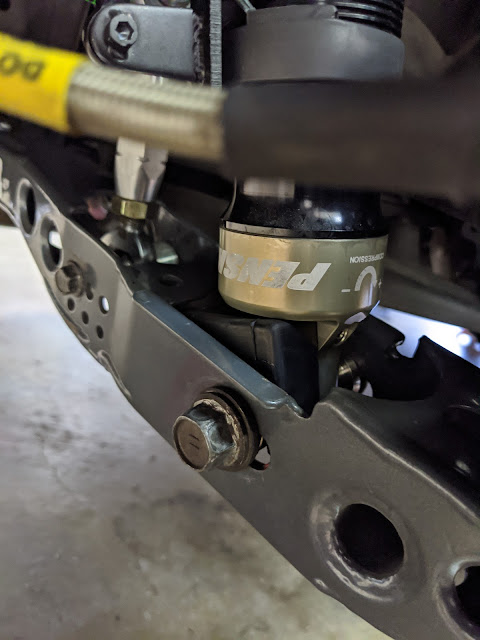
The main things to be done were to mount the shock potentiometers onto the Penskes and figure out what data signals I could pull off of the OEM CAN BUS wires that the car already had built into it. After that I'd need to figure out what sensors I would need to add myself.


For the moment I decided to add the GS dash onto the steering column in front of the rev meter. It was a central location, easy to see and it would be displaying the same data of the things that it would cover on the OEM dash cluster.


Meanwhile, I pulled out the driveshaft and differential for replacement. The diff pumpkin would be going over to Kristian at Battlecraft to add the OS Giken TCD clutch type Limited Slip. I'd have to wait to get it back before being able to add the new carbon fiber driveshaft and replace some driveline bushings.

I also added a solid steel transmission mount from Figs to keep the transmission in place. It definitely transfers additional noise and vibration into the cabin. That's to be expected with the hard mounting of anything, as long as that's the only down side i'm fine with it. Its hard to say if this will shorten the life of the transmission components from the additional shock but I guess we'll find out. I did get a shift selector error after driving it a while on this mount, I'm not positive that that has to do with the new solid mount shaking the gear sensor out of adjustment or if it's just the finnikey nature of the adjustment procedure of the OEM linkage, i'm thinking the latter.


I also pulled off most of the rear arms for replacement with some new threaded steel arms with heim joints that allow for better camber and toe adjustment. The new arms also remove all of the soft rubber from the joints that tend to compress under load and dynamically change alignment settings on track.


The front arms in particular were a PITA. They had these bushings that were made up of aluminum sleeves with rubber surrounds swaged together in a 100 tonne press at the factory. The only way to get them apart was to drill out the center to release the two caps, burn out one side and use a air chisel to get the remaining sleeve out. It probably wouldn't have been that big of a deal if I had some sort of fixture to hold the arm in- but I was working with just a few vices, a deadblow mallet and some torches.


After a lot of sweating and cussing and metal splinters I got both side and both caps out.

After seeing the hearty construction of these bushings i don't think i would ever suggest anyone needs do this to their ISF.

Once I had the races cleaned and greased I used a threaded rod to evenly press the center sleeve into the bushings. It was all a huge pain, but now it was done and ready to go back on the car.


After that I moved to work in the trunk. I wanted to remove all the extraneous wires for things like the trunk popper and contact less key reader that no longer had any function. I also wanted to figure out a way to get the rear view camera on the trunk as functional as it was before.

I stripped and rebuilt the rear trunk harnesses to include the licenses plate lights, rear reverse and brake lights. Everything to make it legal to drive on the road--- well, at least things that wouldn't immediately get me pulled over.

I terminated all of the small connectors on the trunk side from factory and piped everything into a single Deutsche connector. I did the same for the plugs coming off the body side. Now I simply rest the trunk on the back of the car and with one hand plug/unplug this connector and have OEM functionality.

As far as the reverse camera placement I had to cut the provision into the carbon trunk as it was not added into the carbon mold.

But once I had it mounted i had rear picture.

I also weather sealed the gaps in the rain catch


Next up on the data side of things was to splice into the factory CAN BUS signal and pipe it to the AIM EVO5 data logger. I spliced it off of the OBD2 port, twisted the wires and shrank them in an interference protected shield.


Around about now I had a few parts show up from Lexus. I wanted to change my transmission fluid filter since the car did have 200k miles on it. This was supposed to be a lifetime fluid and filter according to Lexus, but i figured it was a good time to drain, replace both.
You can see the plastic pick up snout once you remove the oil pan off of the transmission. This job is messy. There is NO way around that.

You can see that the filter was doing its job, it had seen fresher days.

And the pick up on the magnets that reside on the pan side to scavenge particles of metal were looking fuzzy.

After giving everything a once over I cleaned the pan and magnets, added a new gasket and popped it back on.

About this time the Differential came back from Kristian, I plopped in some new ear bushings and put it back into the car.

I also added a secondary intake tube from the ram air off the radiator ducting up into the air intake.


And replaced the front steering knuckles with new OEM ones. I head shielded the ball joints since I would no longer be running the dust shields on back of the rotors.

And I added the new 2 piece rotors up front saving about 6lbs per wheel of rotating mass. At this point I was still waiting on stuff for the rear suspension before I could wrap up the back.


Now that I had the radio out I went though the Factory Service Manual identified and pulled fuses for anything that I had disconnected or removed (fog lights, defrosters, radio, navigation etc). It took time to test these circuits with a multi-meter as I went. On a couple occasions I found that some innocuously labeled fuse also sent power or relayed something that I wanted to keep and readded it. This is a good way to stop current from flowing to empty plugs where you can- especially in a car that I'm not planning on splitting open and thinning the factory looms. On the fuse box side i wax marked any socket that I had permanently pulled a fuse from so at a glance I can tell what is supposed to be there and what is not.

I'm jumping around on the car, I know, it was only because I was always waiting on this or that to show up so I could finish one thing or another. Ideally when i start on something like the suspension, i like to finish it... and anything that has to do with it before I move on. Unfortunately that wasn't the case this time.
Back to the front.. Now that I had the ducting built and extracting ALL of its air from the lower bumper opening the upper bumper opening was obsolete. In the OEM design this grill basically just blows air onto the horns and radiator support anyways. The only thing it does really is funnel air into the air box via a scoop and tube that bolts just above the radiator.
After looking at my options here I decided to block off the grill mesh with some 1/8 inch rubber. I cut a few pieces of carbon for this originally but the rounded shape of the surface made it really hard to get it to sit right and look even on both sides. The rubber was much easier to work with and has a very 'racecar' vibe to it. I left the Lexus emblem open as it blows directly into the intake tube i described above. The intake should be getting plenty of fresh cool air with the 2 inch hose coming from radiator ducting and this cool air inlet.

Oem air scoop below. The foam blocks sitting on the radiator support direct air into the scoop and are pretty much sealed to create a direct path when the hood closes on them.

Next I cut some carbon side splitters and added them to the side skirts, i went back afterwards and vinyl blacked the indentation on the side skirts. Its subtle but gives it a nice contrast between the carbon on carbon on carbon.

After that I turned back to the interior and took time to get the seating position just right as well as set the harness belt lengths. This is always a process for me and it took me a good two days to get both the passenger and drivers sides juuust so. I had to measure and redrill some holes on the brackets for the exact right height and distance from the pedals. The steering wheel is still about 3/4 of an inch further than id like it to be- but I think ill drive it a few times on track before to make my final decision if i want to look into moving it closer or not.

Toddler seating position... check. I sit really really low in this car. Which is great for the CG.

I pulled apart the interior so I could removed a few things that were no longer being used. I also needed to adjust the shift arm mechanism on the shift box so it would clear the new spacer on the drive shaft under the car. Not hard, just have to take almost everything apart to do it.


After waiting weeks for the remaining parts to be made and sent out I got the last few boxes i needed to finish putting the rest of the suspension together.

I replaced the last few bushing in the rear knuckle. Again, this was a task to do but after some good old backyard ingenuity I got it handled


After flushing the brakes, changing the oil and topping off the transmission fluid I was finally able to put it on the ground and drive it under its own power outside to have a look at it. Before I did that i took the opportunity to adjust the ride height down 2/3rds of an inch.


Front rake is 1.6 degrees at the front splitter. Perfect.


Cars 'race weight' without 200lbs of ballast on just over half a tank of gas. This means that After adding a roll cage, a second seat and harnesses, jack point structure, splitter, splitter mounting, wing stands and wing the car was still over 250lbs lighter than the gutted one seat version with no aero or cage of the last time I had it on the scales.

With the ballast added I got it to exactly 50/50 cross weights.

Man it looks GREAT this low; this car definitely has road presence.

So after putting a few hundred miles on it over a few days I brought it back into the garage and put it up in the air for a nut and bolt check. Everything was good but after poking around on the rear lower control arms I was noticed they have the ability to rotate under load. This is probably fine but, there is an OEM ride height sensor that attaches to where the sway bar sits. the twisting of the rear arm could confuse the traction control ECU and tell it the car is out of control when its not.
You can see the twist rearward here..


I came up with a low budget solution using a jack stand pad. I removed the rear coilovers and cut the 'U' shaped pads in half to the width of the bearing sleeve.

This happens to fit perfectly onto the bottom end of the coilover body.

Once lightly greased and installed the U shape keeps the rubber spacer in place and takes up the slop in the arm.

Doesn't look to bad either. this was a temporary fix that may just stick around. I'm going to be checking it frequently but I really don't see a reason to change it out of its working.


I later blacked out all the mounting hardwear..


While waiting on yet even more parts to show up I polished the car. I NEVER do this type of thing but the paint on this Lexus actually looks great for the mileage... and neglect.

About this time some angled carbon I had made showed up so I was able to build the splitter fences.


I also bonded a 3/8 inch wicker flap on the end, every little bit of drag reduction helps.

It was around this time that the wing FINALLY showed up. It was at the carbon guy getting the mounting points bonded onto the top for the swan neck mounting. Apparently the epoxy needs a super specific mixture and cure temperature to ensure adhesion, since this important as far as safety goes i left it up to the professionals.
But seriously, the wing looks freaking EPIC. Amir came over and we made sure that the adjustment holes work for the AOA's we'd likely be using were working.


It was getting closer and closer to actually be able to take to a shake down on track. Once of the last few things that I would need to do was initialize which data streams I would want to use. AIM is a notoriously vague company when it comes to their products. Basing what you need to do as far as product set up on their online information its especially difficult. "You bought the sensor, great, now you'll also need to buy the wire to plug it in." "Which one? :scoff: Well.. Heres a whole bunch of outdated forum conjecture and zero customer support, let us know when your ready to guess.."
Luckily I had Amir who'd set up a few of these before and could help me figure out what I needed. I bought what i thought was all the appropriate connections so I could run the GPS beacon, dash display AIM Smarty cam, as well as get the relevant data into the Evo5 and out to my display. This first try only half worked. CAN signals didn't exactly do what was expected.
At this stage I had throttle position, revs and water temperature steering and brake pressure, but that was pretty much it. Oil pressure and oil temps were being read by the car somewhere, and we could have potentially piped them in, but it would have taken some under-the-hood software tinkering. After a bit of back and forth I decided that I would place yet another order and just simplify things by pulling oil temp, trans temp and oil pressure from standalone sensors. First thing that showed up was the CAN expansion so I was able to plug in my new smarty cam and allow for it to display some data on an overlay.

I found out on a Thursday before the weekend that there was an event going on Fathers Day at Streets of Willow. It was, however with a group known for on track traffic from overselling events. I figured with the lock down and it being Fathers Day perhaps the car count would be lower. I loaded up the car and got everything ready for shakedown.


Video of the semi clean lap here. Still PB'ed the car with how shit the conditions were. You can see how long I was off throttle in the video- Easily lost over a second in the first 4 corners alone and kinda putted around short shifting the rest of the track. This, again, is frustrating but also a good sign that the car should be fast-fast on a cold November morning with a clear track.
Also- cool overlays now in the videos.
As I was loading up someone came up to me and told me that when i was coming down the straight at speed my hood was bulging and looking like it was about to fly up. He said it had happened every session i'd been out that day.
'Ah, that would explain the overheating' i thought. I knew the radiator, oil cooler and trans cooler were working well in the past, I had a few track days in the heat with that stuff already.. The front ducting was the new thing. I surmised that the ducting is working so well and cramming so much air into the engine bay that it can't exhaust out fast enough. This backup creates a layer of high pressure that stagnates in the engine bay and ducting preventing flow through the coolers. I remember reading about WW1 and WW2 era airplane designs (pertinent because they travel about the same speeds as a racecar.) The rule of thumb for their flow-through exchangers was to have double the size exhausts openings as the inlets. In my hoods case I had some openings, but they were not the ideal size or in the ideal spot to vent radiator air.
The factory solves this by utilizing engine under tray low pressure vents just behind the radiator to release the dirty air under the car and keep and nice clean hood. On my car I have duly sealed all the stuff on the bottom and behind the radiator in order to have clean low pressure flow under the car. The heated air this day probably just didn't have anywhere to go.
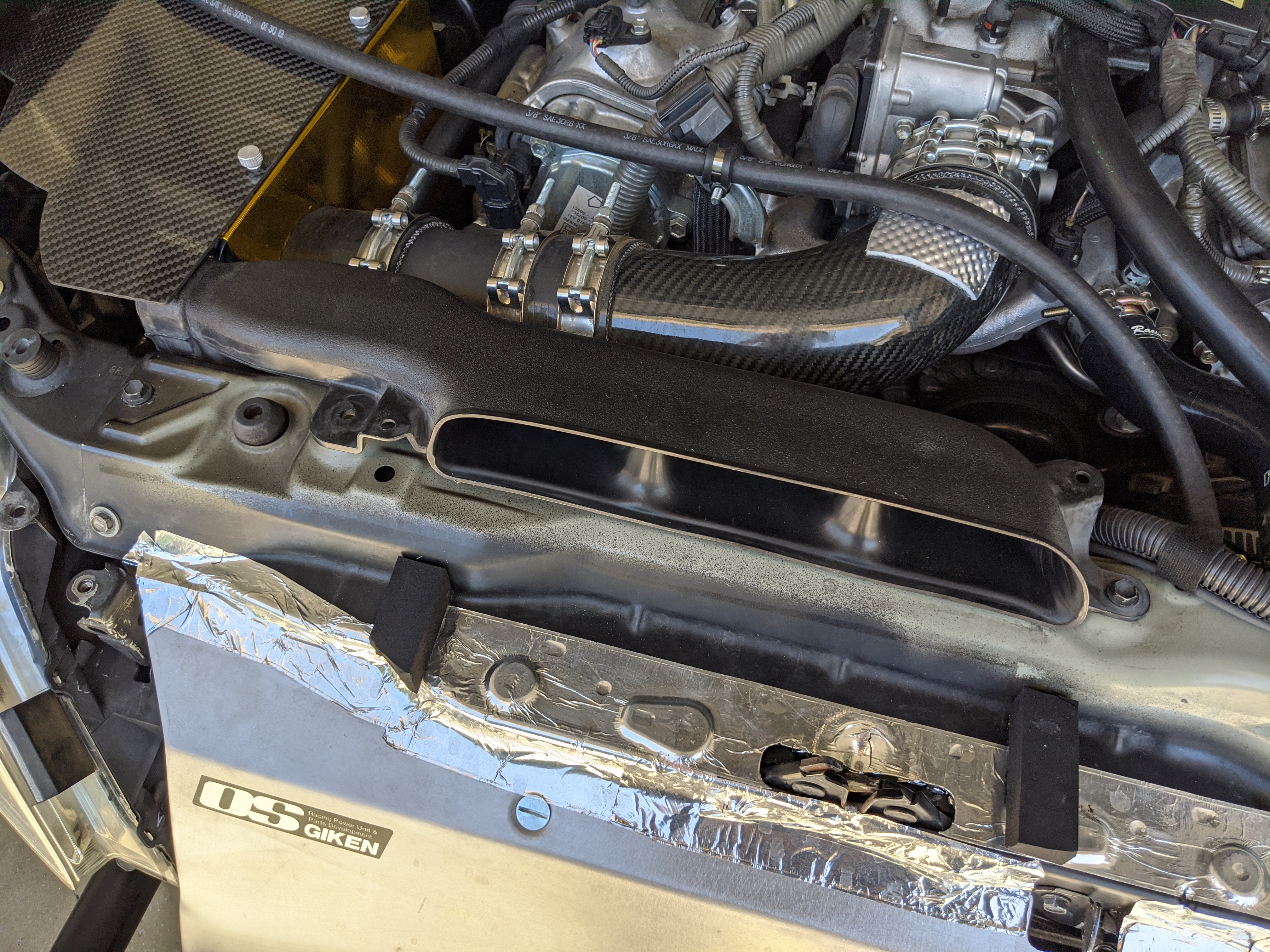
First thing I did when I got home was take a look at how i could help the situation. You can see in the picture below that just behind the radiator is crammed with a metric SHITLOAD of stuff. There are things like the air intake tube which can't be moved- but also things like the OEM pressurized water bladder and the Air to Oil catchcan. I thought even if I added a hood vent it would still be about 80% blocked which would still choke the air to a crawl.

I knew I wanted to move the coolant bladder, but where to? Everything in the bay is such a tight fit that the only room I could find (that was also higher than the top of the radiator for bleeding purposes) was back where I had previously put the mini battery. If I was able to move that to the trunk I could potentially fit all the water stuff in its place.

I decided to get to work moving everything. First thing was to put the battery in the trunk. I wanted the trunk to obviously still be usable so I needed to offset the battery back away from where it could potentially get knocked into by a cooler or a bag of tools. To accomplish this i found some old roll bar mounting standoffs I had. I laid down some thick Velcro padding under where the battery would sit to keep anything from rattling metal to metal.


Since I didn't wanna have to crawl into the trunk if I wanted to attach a charger I added these cool charging leads directly to the trunk frame surround. Heat shrank and booted all ends and tapped and lugged the negative ground directly into the thick roll bar reinforcement plate.


Off of the positive I ran the cables to a new battery master-kill switch that I put in the cabin. I had to find a spot that wasn't too hard to reach but that would also be strong enough to support the switch. I found a spot on the dash that didn't curve to much and bridged the mounting bolts right on top of some reinforcement webbing. It's very sturdy and clears everything nicely on the back side. O AWG comes from the battery to the switch and 2 AWG from the switch to the starter cable and fuse block buss terminal.


Now with the room in the bay opened up I set about getting the pressurized water bladder and other stuff moved. I also trimmed a few spots of plastic off the radiator shroud to allow for the air to vent directly off of the core. I know this makes the fans less efficient but idling in freeway traffic isn't really going to be a problem for this car.


This is the cold side radiator hose splice that will feed the header tank. Pulling coolant flow from here will let the car warm up normally, the other side of the tank will get inlet off the steam port at the top of the radiator. I found a cool local-ish company that makes these fancy billet pipes.


Used conveniently placed m6 studs off the heads to route the waterlines to keep them from contacting anything.

To the right of the header tank is a oveflow tank. It's purpose is to allow me to overfill the header tank so as the water heats up and expands it pushes air and coolant out the spring cap neck and into to the bottom of the overflow tank. The air escapes out the fitting on top but the water is collected. Once the car is shut down and the water cools the pressure in the system is reduced, once the ambient pressure and vaccume pressure exceeds the spring on the coolant cap it draws water back from the bottom of the overflow canister into the system. Its is a very straight forward clean way to continually air bleed the coolant.
The silver line is temporarily draining into a tin canister for the first few high heat cycles. Normally if this were just water I would let it dribble onto the ground or whatever; but i'm currently still using Lexus coolant and this shit is super sticky and leaves a pink residue like melted cotton candy which I don't want to be cleaning off everything as i burp the system and get the levels right.

Now I had to move the Air Oil Separator. The ISFs have a pretty cool factory oil separator plate built into the valley of the engine, it works well enough that the factory race cars don't run a separate canister. I contemplated not using one anymore either but remembered back when I first got the car and did a test.
I cleaned out the throttle body, went to the track and checked it again when i got home where I found oil pooling directly before the intake runners. Its not the end of the world; and at 200k miles its to be expected that the rings probably aren't as tight to the cylinder walls as they once were- add to that the compression ratios these motors have from the factory and its obvious recipe for blow by. Instead of not running one I decided to get a much larger one to give me more time between empties.
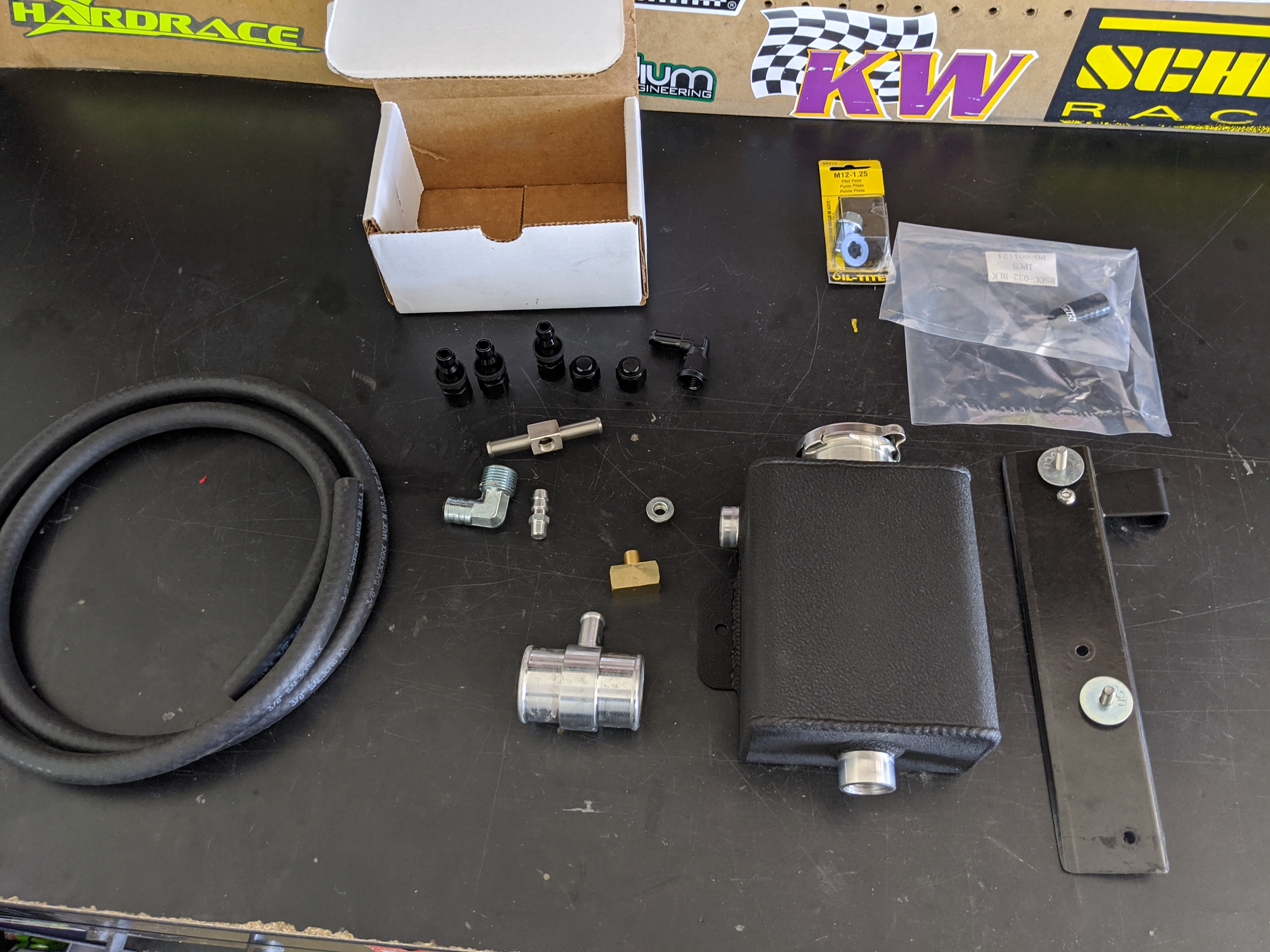
I picked up a 1 qt competition catch can and AN fittings. It is a bit weird how the factory used two different size hoses for the venting and recapture, obviously the bigger the hose the less the air velocity, the less air velocity means the less liquid oil gets moved. I may look into up-sizing the smaller hose in the future. I attached the whole new fixture to a spot once used by the windshield washer bottle neck and attached it to the chassis with a carbon fiber tab.


I also sealed their leading edges off with bonding for a more clean look.

Between these and the top vents I should be moving quite a bit of air out from where it would just be causing lift. I should also see gains in front brake cooling and the efficiency of the front splitter diffusers.

Once the rest of the AIM parts came in I could go about wiring up the remaining analog sensors for the data acquisition unit.

After installing the catch can I went ahead and added some additional low pressure vents to the fenders, this will massively help to relive high pressure lift from inside the fender wells. I inserted the mounting flange up from the bottom attached them, then weather sealed the gaps to the fender itself. This whole mounting was a major pain in the ass since they needed to be twisted to follow the rounded contour of the wheel arch.


Did exactly the same on the passenger side as well.

To help the air extraction even more I cut some wicker bills and bonded them to the side skirts just in front of the openings.


For the new oil pressure and temperature sensors I tee'd off the OEM pressure port and left the oem oil temp sensor alone. I did it this way because the oil temp read out on the OEM dash would blink annoyingly if unplugged. Id rather keep it doing something that i'm not paying attention to over blinking continuously while I drive the car. The empty plug of the pressure sensor was zip tied up out of the way and heat shrinked in red to denote its unplugged on purpose.

After determining which hose carried the cooled fluid back into the transmission from the cooler I pinched it and installed the 3/8 to NPT junction.

Otinker clamps for the hoses on the barbed ends and installed the sensor. After doing this I actually went back and installed another npt/npt spacer to pull the temperature sensor nub out of the free flow of the fluid, just to be safe and not cause any flow obstructions.

Once I had all the sensors installed I had to run all the cable lengths though the fire wall and back to the data unit. This is always a mix of fun and total pain in the ass to get everything to feed cleanly though the grommets. Once they were installed I went back and did a pass on chafe points and added split loom to hold everything together and match it to the OEM wiring harnesses.

While the dash was apart I took the opportunity to run micro bridge switches for the ebrake and the brake pedal signal. After some reading I had learned that the traction control system will maintain the function of the 'brake assisted' E-LSD and some other things even if you've turned the traction control and VSA systems OFF. This system is one where the car senses wheel speed differences at the drive wheels and, among other things, apply caliper force at the wheel that it senses is spinning. This helps deliver traction to the outside wheel even though the car was not equipped with an LSD from factory. Its a surprisingly well functioning system on track (I was 5 seconds faster in testing with it working its magic than without) The only way to disable this ELSD function is to do what is called a 'pedal dance'. The pedal dance was basically the Lexus lawyers and safety engineers building in a "You know what your asking for, right?" sign-off before the car will just let you smoke the rear tires to oblivion.
In my car, now that I had a clutch type Limited Slip Diff, I would no longer need the help of the rear brake pad killing caliper drag ELSD. Theoretically both of my rears should now be spinning at the same time, which you think shouldn't trigger and VSA assistance... but the more I read about the system the more I realize that it also does some other weird stuff with the steering, brake pedal and throttle control to help keep grandmothers out of snowy ditches. I decided it's best that I just shut the entire thing off when on track and drive the car myself.
The pedal dance is something like 2x press and hold X pedal, 2x press and hold Y pedal and so on for 3 rounds. You get a flashing light then the system shuts off. Easy enough when the car is stock but now that I had installed a full containment seat, the ebrake pedal press was sort of a task to get your foot up onto. I added these jumper buttons to trick the stability control ECU that I was pressing the pedals even though I am now able to do it very quickly with my gloved hands while strapped in with a helmet on.

Whats more is now that the 'pedal' is a button, I could removed the actual e brake pedal. I never liked having a floor mounted pedal in a track car, its in the perfect spot to brake you ankle if you come into contact with something hard enough. Mine wasn't even hooked up anyways, I pulled the rear drums out of the car for unsprung weight savings a year ago.. Bonus was saving almost another 4lbs

Now with the wire bunches run I installed the expansion harness and wired in all of the sensors.

I also decided to move the display off of the steering column. On track I realized the aftermarket gauge felt to close to glance at quickly and it was blocking the traction control lights on the oem cluster. While strapped in I couldn't tell if the lights signaling I was in 'sport mode' were on either. After playing with different mounting spots I settled for the drivers side air vent. I removed the vent sealed the AC duct that fed it, and attached a mounting bracket to the touch screen console surround.

I cut a carbon fiber finishing plate for the vent hole and neatly ran the connection wires behind the dash.


The final part of the plan now was to actually install the hood vent. UPS had lost the part and it was about 2 weeks behind schedule but eventually made its way to my door. I had picked up a stock hood from Sean's ISF and cut out the internal ribbing, funny enough the weight of the stock hood without the internal ribbing was a pound lighter than the fiberglass/carbon hood i currently had on the car.

After a whole bunch of mocking up and measuring I cut the holes id need into the hood.


Topside flange mounting

I then trimmed the scoop wider to allow more air volume to be flow.


And finally sealed all of the edges down to the surface of the hood to keep them from bowing and looking shitty when they heat up while on the car. It really looks nice to have the edges finished in this way. I had to use more rivets than I wanted to originally because the hood skin is so thin you could press it down at the gaps between vents and they would easily separate from the each other. Just a few additional rivets made everything much more rigid.

The duct starts even with the front edge of the engine block and ends just above the throttle body. Now there is PLENTY of room for the air to leave the radiator unobstructed. I should hopefully see benefits in the oil, water and trans temps as a result. Stepping back and taking a look this thing should flow some serious air. The fix was pretty involved and touched many overlapping systems. I like things like this, where a solution isn't always straight forward and takes a bit of engineering to try and fix something cleanly. There is room to add a few more vents if I feel like I need them, but I want to test it like this first.


Now that I had the top radiator exhausting sorted I built some test block-offs out of alumilite and integrated them with the oem transmission cover. They now extend down the floor well past the firewall. I'll see how this all works and replace the alumilite as needed to with some of this sandwiched carbon I have. That red painted spot is the jacking paint of the subframe.

Last few things I did were to build profiles for the camera data layouts and the Dash screens. I also added sensor warnings and lap data how I wanted to see them while on track. I re-calibrated the steering rack torque computer and sensors with Techstream software and to be safe added a new throttle pedal after seeing small hiccups in the data from the throttle position sensor. Its crazy how much you need a laptop to work on a car from this era forward.

Next up is a track test. Hopefully this heat goes away soon and events start happening again. I cant wait to take this car around SoCal and see how it does. As always, i'll post back here when I do.
This comment has been removed by a blog administrator.
ReplyDeleteThis comment has been removed by a blog administrator.
ReplyDeleteThis comment has been removed by a blog administrator.
ReplyDeleteThis comment has been removed by a blog administrator.
ReplyDeleteThis comment has been removed by a blog administrator.
ReplyDeletePretty good post. I just stumbled upon your blog and wanted to say that I have really enjoyed reading your blog posts. Any way I'll be subscribing to your feed and I hope you post again soon. Big thanks for the useful info. 2022 tacoma grill
ReplyDelete