Alright. Been a while and I have tons to get down. Crazy past few months, not only with car stuff but work too. My normal work schedule is from 830-730 every weekday at least one Saturday a month. Being a Head Of Department at a tent-pole movie studio requires me to creatively touch every shot that passes though. This means when work's crazy- i'm crazy and have even less time than normal to work on the car.
Crazy its been.
Most of the work here in this post was done between 8pm and 3am on the weekdays with the occasional weekend day spent picking up parts and doing everything else I need to do too keep my life together. Doing anything to this extent is a commitment of both money AND time- this leaves the builder feeling as if the sum is greater than that of its parts; or what can just easily be added together from receipts. In this case, I feel with my CRX that the largest investment has been my time. (it trumps even the large cash amount I've sunk into this endeavor) Time I could have used to explore other things i have instead chose to spend indoors on the computer or in a cold dusty garage that reeks of chemicals.
I frequently think back on when i had bought the car as a 'side project', i wanted something that was 'ready' that i could track while I built my AE86. I really honestly never intended to get so deep into this chassis. I've never particularly liked the CRX, this just happened to be the most 'ready car' i found after about a week of looking... and what I did plan to do on it was strictly thought about only in the dollar value sense. I chuckle to think how many man hours have now been sucked into this 'side project'. Not just me wrenching but all inclusive. The time I spend working my 9-5 to pay for the parts i buy etc. I wonder how much percentage-wise it would work out to if you could start the timer from the moment I bought the car. Maybe deduct the time I'm a sleep... I don't know but its got to be A LOT.
I do this to myself, though. Something that you put this much effort into should be done correctly. Good enough can always be better and with age I'm coming to terms in understanding how insane I am about particulars.- Which makes the whole building this "car i never really wanted" to such an extent a sort of Roman recovery Comedy.
--------
I'll just have to jump into this edition I'm hazy on the order things went, not that it really matters but i've at least tried to keep it as chronologically accurate up to this point.
From where we last left off I had just finished the harness and while the car was away at the fab shop I pin tested each lead again to make sure things were going where they were supposed to go.

During the testing as a sanity check I stripped parts of the T- off's from the outter loom so id be able to verify wire color and which branch they went too, this would make 'on car' trouble shooting much easier if it came to that. Im going to go back though and wrap the main joints after verifying everything works as it should. This was probably an extra step, but was better to do it now when it off the car and I had time.
 |
| I dont think i ever posted a picture of the finished loom |
 |
| detail of the plug end wrapping |
Meanwhile I used my hackey circuit board program iterate and really refine the wiring. I had a few ideas about how I wanted it all to work but actually laying it all out it tangible 3d space is a different thing all together. The first few versions of the schematics were more of a proof of concept and a place to get the ideas down so I could trouble shoot potential problems or discover better ways to route something. I'd then work on each arm of the circuit with first priority obviously being on functionality, secondary being simplicity and economy of space where third would be aesthetic layout.
 |
| early iteration, main loop schematic. Purpose here was to figure out Deutsche connector pin count, clip type and wiring size |
 |
| Probably 10th iteration refined layout and nailing down specs. |
I also did a few color coded schematics for my files so I can go back in the future and reference them when this is all not so fresh in my mind. At this point I can Rainman style recite functions, wire colors and their routes in my sleep.
 |
| This was mid tool up. The bummer with Deutsche connectors that that i have yet to find a local vendor, if you forgot to order a part youre dead in the water while you waited for it to show up. |
While I was doing all that previz work I ordered an OEM 4.7 type R b18 final drive kit. I also got a new 1st gear and the needle bearings. To go with that I also ordered a Mfactory Clutch type LSD too. These some of the things I'm most excited to get on track and try out.
I've never owned a clutch type on a FWD car, but i've had a few of them of MR and RWD cars in the past. They're always a game changer if you can adjusting your driving to utilize them. I had a Helical LSD on my DC5 from Mfactory which I liked very much and has me expecting the same quality here. I'll have to run the LSD bearings with no face plates to allow oil to flow through to the clutch pack for cooling. Clutch type also requires more frequent trans fluid refreshes- Its a track car so these things are expected.
Up till now I've been running the 4.4 Final drive ratio. beh. 4.4FD is not the greatest for the power band and torque curve of the b18- especially on the tracks that the car regularly sees. When I swapped from ratios on my NSX to the JDM type R spec I dropped a whole second at Streets of Willow on the first outing and even more time at Button. This excites me because if this holds true on the CRX ill be right in the wheel house of my target times.
 |
| new OEM goodness |
To address the Coil pack hitting the hood issue I decided the best thing to do was get a shorter set. I had a few sets of s2000 coils and a set of K coils around that would have apparently worked but they would not have had the ideal seating in the valve cover. After talking to Hondata I got some D series coils and plug gaskets off of a J motor. Stupid gaskets alone are 20 bucks a piece- Rip off but still cheaper than hydro locking or detonating a motor from water diluting the fuel.
 |
| Dem red labels.. |
 |
| length comparison k20/s2k on the right new D coil on the left |
After getting everything as far as I could without the car here I had quite a bit of down time. Over at the fabricators SEMA builds were the priority and my car was pushed around until all the big projects got finished and sent to Vegas. Its a bummer, sure, but this isn't my first rodeo. I'd much rather deal with waiting some extra time than have someone slap something on my car in a rush just to get it out of the door. As long as there is communication and my expectations are met I'm a pretty patient guy.
Meanwhile I took the NSX out to Thermal raceway to drive as an instructor at NSX expo. After 6+ months I finally got to get on track again with it, it was double cool to be able to do it at an invite only facility. It had been a while but I shook off the rust and threw down some quick laps. On the drive home I decided the benchmark for the CRX should be to handle like my NSX. It took me a lot of experimentation and tuning to get everything dialed on the NSX but its turned it into a very rewarding car to drive fast.
 |
| On the way to NSXpo |
After being unimpressed with the new NSX and hanging out in the zillion degree Palm Springs heat I came home and decided to make it less garish by removing some of the more 'loud' boy racer parts. I swapped the GT wing out for my type R wing removed my oil cooler and sump kit. Also swapped back on my Titec diffuser to give it a more 'low key' profile. It feels right setting this car up as more of a weekend fun car. All of the spherical bushings and suspension is staying the same but as far as appearance and street-ability I want to have is as something that looks less like it just pulled into the hot pits at Twin-ring Motegi and more Sunday dinner with the GF appropriate. Best part is the car will still run a 1:22 at Streets in its 'low key' format.
 |
| Street spec version |
Finally after a long wait of obsessively building schematics, collecting parts and general neurosis I got the car back from the shop.

I 'd normally hate the idea of someone else doing something for me that I could do but Steve has the right tools and he knew what I was looking for. Also I'd rather pay for something to get done right, and when it comes to something as important as a fuel line, there was really no other option. The trick was to be able to run the lines in a way that would allow for me to route some pretty thick looms and power wires underneath them. This was made more difficult because I didn't know exactly where I wanted stuff to route. so everything had to be done in a way that left me the most available options.
While the car was away I also had some stuff powder coated. It really adds to the whole quality feel to have a good uniform finish on things, especially when they are so few in the cabin to begin with .
 |
| Fuel and brake like run down the center of the car for maximum safety from impact. Black powder coat applied. |
Below you can see the bulkhead connections for the two rear calipers going up and over my coolant fill tank. The fuel return line comes out of the rail and via softline to the side of the FPR. It exits back to the cell though the hardline coming out the bottom. The soft line just below that in the firewall is the Feed line coming from the pump. Obviously anything connected to the fuel rail needs to have some flex to it to account for the engine movement through the motor mounts, hence the soft line in these two cases.

Now that I had the car back and had spent time staring at everything i was ready to get started.

I had set up a work station on my bench where everything was at hand. Again, like with the harness, i found the best method to work on only ONE circuit element at a time until its completed then test it and move on. This may feel slower, especially when the heat gun is already out and warmed or you feel like a wire crimping machine.. I'm convinced a methodical approach saves time in redo's in the end.
You'll notice the quality of the nickle palted wire after its been stripped. The strands are substantial and tightly wound around each other with no deadspace. Good wire is essential when crimping into Deutsche connector pins as they are a friction interference connection type and require a tight wire bundle to clamp firmly onto


 |
| Once of many test fits for wire lengths on the main control panel |
 |
| Finalized breaker placements with spliced bundles going to +12v power source. |
Typically, a standard master breaker is used only to connect all power functions with a +12v source (battery). Its a simple two state on and off like a light switch, however a car with a alternator is not like a light. A car can run solely on the alternators output, even with no battery connected. In running state, if the main continuity is interrupted the generated with build power in coil and it runs back down the cable to the master switch and can surge all connected circuits. This can very easily cause large amperage spikes that will burn out the switch itself or worse- fry the ECU or other sensors. Not good.
This new switch, in addition to the standard 12v hot and 12v cold switched power posts also has two additional contacts that toggle positions in concert with the throw of the main switch. One set of contacts (Z) turns "On" when the the two main posts have continuity and the other turns "On" when the main switch is "off".
Basically this switch solves 3 different functions with only one user input. First function, like the standard switch is to connect your main 12v power (like a light switch- on/off). Second function is the same but it connects power between the (Z) leads which provide the distributors ignition signal. When the main switch is flipped "off" (Z) also loses continuity and the car will die because there is no power to get spark. This breaks the cycle of the car being able to run with no +12v source (battery) attached- where the alternator is making enough power to fire the spark plug which is in turn causes ignition and spins the alternator fast enough to generate enough power to make another spark... and on and on.
Lastly by using the (W) contacts that turn "On" when main power is switched "Off" allows you to bleed the previously mentioned surging power to a safe ground away from harm. You simply need to loop once side of the lead to the battery lug and the other side out to ground through a ceramic resistor. You can see in the picture below i had stared to wire the grounding lead.

 |
| ceramic resistor to handle the potential ground load while bleeding down the alternator |
After getting the wires shaped up on the breakers panel side of things I had to connect the power and grounds and signals to the Hondata CPR. The power for the Coil-On-Plug ignition I would need to route from the COP box through the main battery switch (as described above) then through a the 30A fused breaker switch and finally into the each coil.

Here a picture of the +12v PGRM wire on the back of the ECU that I stripped to splice 12v power the COP box. You can see the heat shrink id already applied to the wire that will provide grip for the second shrink to seal in the wire splice.

Below picture is a little dark but you can see the connection had been made and glue wrapped between the other shrink. The mini zip ties relive any yank pressures the splice itself would normally have to deal with.

This picture gives a good idea of my work space. Not a ton of working room but better than my last place where I built the NSX. One day (sooner than later) ill have a proper shop space.

Next on the list was to provide power, ground and signal to the gauges. These were a bit tricky because I would need to also route the looms from the engine bay sensors and have everything meet up as tidy as possible.
First step was to install the gauges into the the dash plate that had recently been powder coated. I was pretty stoked how clean it was starting too look ascetically.
Orange light is for the ST200 Tach gauges programmable shift light. Red light warns of any oil related problems. Those are accompanied by different flashing patterns and beeps telling me whether its pressure or temp. The blue light I had originally wired the same, but decided to install a water pressure sensor similar to my NSX instead. This will tell me if the water pressure in the system drops below 5psi. When illuminated it'll mean either the engine is not up to operating temperature, where the heat has pressurized the sealed water system to over 5 psi. Or, If it does come on when the car is clearly up to temp, like while on track, it means i've sprung a leak in the water system.

Again one of many test fits to determine wire clearance and lengths.

Signal/ground wires and ground/power can be run through the same connectors, Since they only fit together one way and are totally isolated from each other you can economize connectors all you want. I personally avoided running any high current lead wires next to any signal wire to avoid potential interference. The SPA gauges actually have triple insulation on the signal wires so you' be able to do just that if needed too. I love a company that doesn't take short cuts.

I also cut and mounted carbon fiber plate over a rubber mat the length of the battery position. This is to avoid any potential arcing to the chassis during installation and use.


All the Deutsche connectors rest on clips that rivet into place to keep everything nice and tight, these keep the wires from jiggling and causing an intermittent connections. I'm admittedly OCD about this; I HATE when things move around, clunk and make noise when i'm inside the car. If something 'clunks' I want to hear it, and take it as a warning, not just pass it off as "oh its just the cables hitting the door"
 |
| in the picture id yet run fuel relay signal and break switch power |
 |
A big moment of truth came with it was time to energize everything and see it all light up..

Relived it worked- next up was to finish the fuel pump wiring. To do this I would need to build and dry install everything to accurately measure lengths to deduce proper wire sizing.
First step is always to flesh out where the main components go and then build the bridges between them.
I had decided to run a fuel cut of switch after reading about them on the Porsche race cars. Basically they work similarly to a 'earthquake valve' on house gas line. Inside the switch there is a magnetized perch that a metal ball sits on, when the ball is in place on the perch it completes continuity and power flows. If there's an accident or shock over 9G's it rattles the metal ball off its magnetic perch thereby breaking the current and killing the fuel pump power. In the event that the car is hit hard enough that I was incapacitated or in a hurry to get out I wouldn't have to remember to flip any switches to kill the flow of fuel. Resetting the ball is as easy and pushing the Huge red button plunger on the top. All the cars in IMSA run these switches at Seabring- which is a notoriously bumpy track and none get false trips.
To mount my switch I needed a extremely stable platform at as near perfect 90* as I could get.. since there is non within reaching distance of being strapped into the seat I had to build my own.
I bought a super beefy 1/4 angle of non weave pressed carbon. These are made in a 250ton press. Bonding agent and carbon are mixed then squashed into shape and super heated. The tinsel strength of this piece is pretty incredible and will be as rigid as it gets when mounted to the steel.
To make it all nice I first had to measure the angle of the sloping metal where I was planning on placing it then cut it down so everything measured out at right angles.
 |
| after a bunch of measuring, before the cutting |
 |
| After cutting the carbon and mounting the switch. Very Very solid with 9 3/16 rivets in place. |
The 'big' power for the pump itself will come directly from the battery with the fuse in optimum placement on top of the power source. The fuel switch above is wired in this path and everything from here back is connected with 10AWG wire from start to finish. For these heavier load set ups I decided to use the same insulated Kevlar sheeting I did on the engine loom coupled with thick 4:1 raychem DR25 wrap.
I'm also routing the brake light switch through some Deutsche connectors and powering them directly from the battery as well. Doing this will let the brake lights work independently of the master switch position, this means if I lose power on everything else ill still have rear brake lights. Solutions like this separate track beaters from track cars.
 |
| Fuel main power switch feed. Pre-wire wrapping. (fuse replaced with 25A). this all has a nice plastic cover when in place. |
Now that things were getting closer I decided to hard mount the battery with incorporated 100AMP fuse and run the lines for the fire pulls.
I was able to trim the pull wires and cleanly run them unobtrusively through the dash plate and around above the firewall.

You can see the layout was pretty much finalized here. After placements were sorted I could start to wire everything up..

...And a shot of it all wired cleanly. Its looks easy when its just a before/after photo set but just this rear section represents quite a bit of time.


The wiring for the brake lights run back and incorporate into the same harness as the main fuel pump power.
Close up of the fuel relay and fuel switch wired up; Carbon fiber backing between the relay and the sheet metal.

Now that this section was done I could move farther back and get the power to the pump and signal to the rear lights where they needed to be.
The power for the pump was relatively straight forward but I went back and fourth on the pros and cons of grounding the Pump back at the battery vs grounding it to the nearest solid earth (in this case at the bumper frame). After a bit I ended up using the m6 bumper frame bolt. I bought two thick copper washers stripped the surface then and sandwiched a thick ring connector between then. I'm pretty confident that this was the best way to go.
 |
| before getting to work on the lights |
 | ||
| Bad picture but a better view of the grounding lug and loom placement. |

Above is the connection detail on the pump with no lid on the box. The fuel line
holes will be sealed tight with ring gaskets, you can't
see it here but the wrap line is sealed with Raychem dr25 where it
passes though the metal.
Before wiring the rear lights I went and removed all the extraneous connections and bulbs. I had no more turn signals, running lights or reverse lights wiring so I stripped out the bulbs, clips and OEM wiring then blocked off all of the light holes that would wouldn't be using anymore. These were literally the last OEM wires in the car . At this point I had removed everything not needed and replaced what was with my own.

Once that was done I went through and finished connecting the lighting branch of wires that i'd already integrated into the fuel pump harness forward to the battery.

Bulb provisions block offs really cleaned up the rear hatch area. Nevermind the rear trunk tumbler in this picture. That has a block off plug that is going in its place.

By now the interior was getting really close to being done. I had tested my circuits and had Katman come over to initialize my Hondata for the CPR and transfer a fuel map that would allow the car to run and drive when it was time to break in the clutch. Thankfully everything came back green on the systems check and I was able to get spark. I have yet to fire it up and run the car but all the signals were getting to where they needed to go according to the laptop and dummy lights.
I routed the push buttons for the gauges and decided to move my lap timer from the center of the dash to just above the breaker switches. I also installed some grip tape in the foot well.


To keep me from accidentally kicking anything important i also whipped up a carbon divider for the foot well.


Now that i was kinda finished for the time being in the cabin. I could move onto the engine side of things. First I needed to cut the tabs off of the new coilpacks so I could fit them in the valve cover.

After using a cut off wheel I used a sculpting bit to smooth down the plastic. if you ever have to do this; get this bit, its messy, but it makes the job much easier

My newly built wiring harness- all plugged in with the new coils. The 20 dollar a peice coil gaskets made a HUGE difference in holding the coils firmly in place.

 |
Again- all the battery cables are an overkill at 1/0AWG and i have wrapped everything with chafe proof insulation and heat shrunk all exposed metal that carries a current. All these pictures are from the test fits- final placement will all have insulated motorsport boots covering the metal leads.

 |
| -3an fittings to the rear brake lines as discussed above. Hokusai wave sticker from Japan on the water canister for good luck. |
Below is the obd1 alternator plug. I removed all the connectors that I didn't need but left the Control and the (IG) Power wires. The (IG) Power wire i talked about above, for the Control lead I'm trying something a little different. I have been doing a bunch of research about Hondas variable charge state alternator- without getting too deep into it here, suffices to say that its a very smart system. Basically the alternator looks for ICM input to determine the charging needs of the battery on a normal car- things like defrosters, headlights, fan switch etc all place extra load on the battery which requires the alternator to increase its charging voltage from the 12.8V range up to 14-16v. When the listed items are off (or removed like mine) parameters inside the ECU permit the voltage from this wire to be pulled to ground. Doing so lessens the field charge on the internal coil which reduces the magnetic drag. This frees up around 25+% of the drag on the alternator. Freeing any drag off the alt frees power from the crank and when talking about a 1.8L liter engine you can regain a decent chunk of power just by removing engine drag.
To test my theory I wired up an non permanent test switch to ground that will allow me to experiment with the car on the dyno. Im about 60/40 on this working- one of the parameters the ECU is looking for is a tach signal "less than 4k RPM".. Since going COP running direct injection I have no tach signal going to the ecu, im curious too see what happens when the control is grounded and the motor is above 4k RPM under full load. SCIENCE!
Worse case, I drain my battery finding out, best case I get free HP by toggling on and off the drag from my alternator.

 |
| Ninja switch |
Never having been happy with the waterneck connection, I decided to fix it before it became a real problem. The sensor bung takes my water temp coming out of the t-stat just before the radiator. THIS is where you're supposed to be reading temps people.

And an after picture of it welded watertight into place. I also cleaned up the grounding provision for the new coil packs on top of the housing.


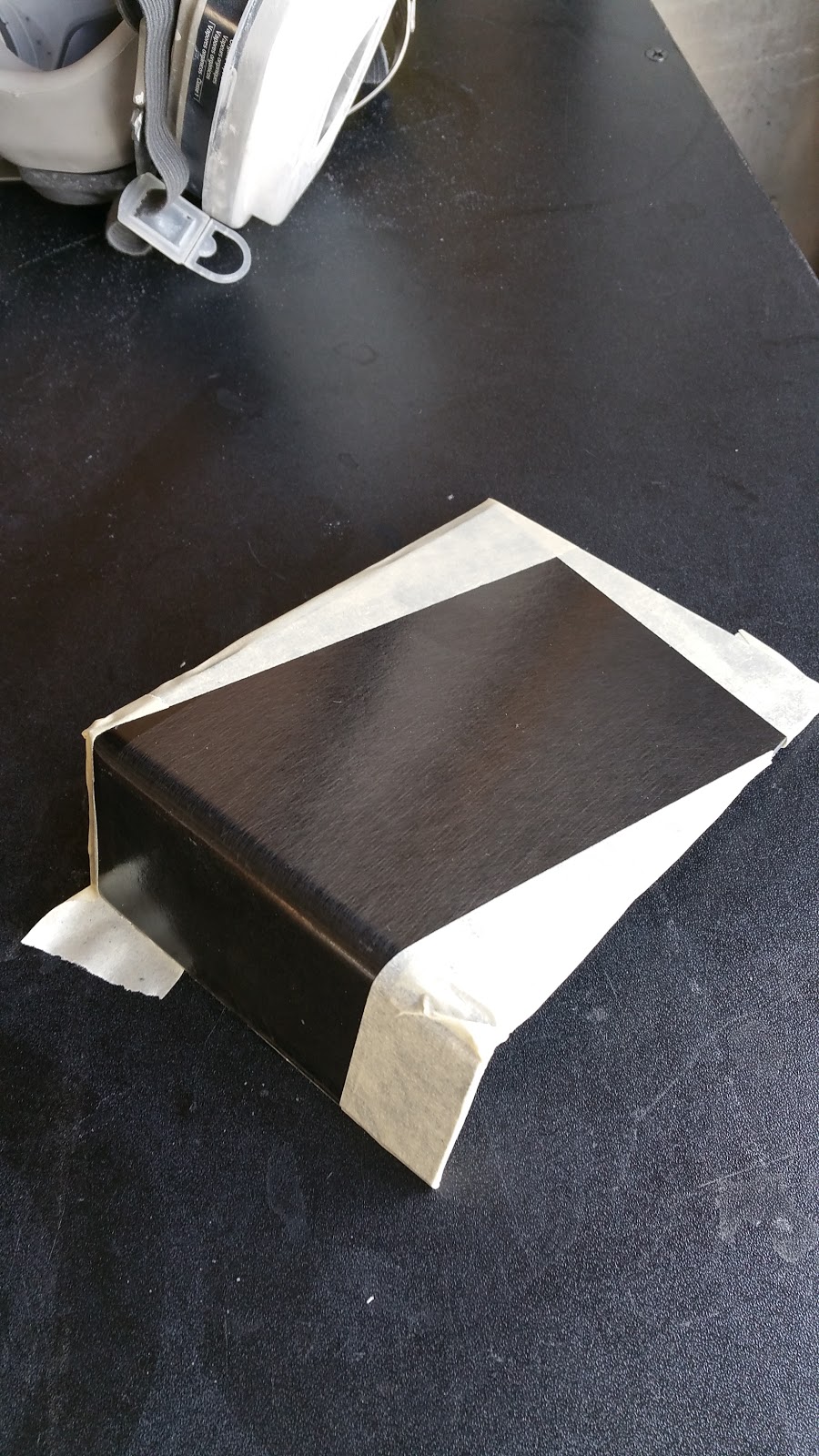
Next up I removed the hood hinges and striker from the bay. I decided to just make the hood fully removable so I could save some weight and really dial in the hood angle when it comes time to vent the radiator. I had to clean up the goop Honda uses to seal the hinges from the factory and give it a fresh coat of paint. Its the shiz like this take just takes time and patience.


I then gutted the skeleton from by carbon hood. This hood is a bit thicker than a standard CF one since its a carbon overlay on a fiberglass honeycomb. This was actually beneficial for me since it adds just enough rigidity that i didn't have to build some longitudinal supports.

 |
| this support weighted a good 7-9 lbs as it was THICK with fiberglass resin and glue |
Once that was done I took out the in-cabin pull lever, cable latches and grommeted the holes left behind. I then installed two Aerocatch pins up front and 3 mini latches in the back.
The Aerocatch latch arms need to be flushed to the hood to indicate they are clamped down- In this way I get a good visual que even while buckled in from the drivers seat that everything is sealed up and ready to get on track. Almost nothing more annoying than having to unbelt and hop out over the cage because your not sure if you closed your hood all the way.

Look at how tight and clean that dremel work is. After slow-going wiring for weeks and weeks it felt awesome to tackle projects that i could actually see get finished that same night.


For the rear I used mini latch push button clips. I drilled and tapped the OEM m6 metric hinge provision and re threaded them with 1/4 20 to accept some extended quick latch posts that I had left over from building my NSX's splitter. The posts were a bit too long so i cut them down to size for a clean install where i'd only use the threads that I would need. I also cut and braced the rods with thick steel dowels I had and capped it off with thick rubber doughnut to give it a positive tension. Didn't snap a pic but ill get one for next time.

You can see the mini latch in the upper corner of the hood below. There is also one in the center so the hood wont buffet up and down around while on track

After installing the hood I was able too finally finish my carbon lights. They turned out pretty mean looking and are super solidly mounted. I came up with a pretty cool tension system on the back side to give them a little flex when closing the hood. Again, unfortunately didn't snap any pics- but its pretty cool.


In the picture just above you can see the induction scoop for the airbox that i briefly touched on in one of the last posts. I'm still working on it but everything is coming together nicely.

With the 3 inch filter attached. 

sticky doubled sided rubber crush foam applied to the lip.

Detail of the welding and grinding on the outside corners of the box..

Gold foiled to avoid heat soaking it while in the hot pit at idle. The 3" inlet at the bottom will meet up with the air intake in the bumper via tubing joint. This is the part i'm still putting together

Finally, here it is Sealed air tight with the attached gusset brace. This will install on the radiator support just in front of the passenger side headlight space. I didn't have it on for these pictures because I took them while in the middle of removing my transmission..

It was sent off for the LSD and FD work that I talked about above. Once it gets back ill have to fill the fluids set the Fuel pressure and fire it all up. Im hoping this all works because
I';ll need to break in the clutch plates and swap fluid before the car can go on the dyno for tuning. If I dont i'll risk damage to the LSD so this is a somewhat crucial step that im hoping everything goes off without a hitch.

 |
| Just before bringing it over to Katman |
I was lucky enough to get a set of Kingpin "outlaw" front LCA's with the upgraded New Hampshire Bearings pressed in. These parts are not cheap but are fantastically done. I'm waiting on the rear set to be made and sent my way to. Its a bummer that i have to go back and repurchase everything in spherical- but i think it'll be the right thing to do once I start to really dial the car in. A plus side is ill have a full spares set up of arms and links with new bushings pressed in ready to go just in case.
 |
| hardrace vs next level |

OKAY seriously, enough for now....
Until the next installment of trying to turn a CRX into a GT3 racecar... see ya!

