So after moving to the new house the plan I'd set in motion a couple years ago when i bought the Spoon car was finally coming into focus. I knew that I didn't want to start anything on the car until I had a place where I can take my time and do it right. The older I get the more I realize things like building a car how you want just take the time they take. You can set yourself goals and stick to them but there is always a certain amount of flexibility you'll need to build in if you're taking on anything substantial. And no, sorry- putting lowering springs and swapping wheels is not a 'build'; i'm talking things a bit more involved than that.
I knew back in 2015 when this thing popped up that i just needed to secure it. I had no place to work on it or any idea what i wanted to do with it if i got it- I just knew that I had been following it for so long and was in a position to purchase it that if i didn't, i would regret it forever. Of course, when I did end up buying it I was already in the middle of some other pretty intensive builds and I didn't have the time or the space so the Spoon car bounced around some pretty understanding friends houses. Arman was good enough to hang onto it for about a year, his house was close enough for me to drive over and work on it on the odd weekend if he was home. Once he switched jobs and needed the garage space to store his new work vehicle Jared stepped in and offered his space out in Riverside. This time a bit further away so I pretty much didn't get a chance to see it outside pictures for about another year.
I don't know if its because its SpoonSports car and all my friends are as suckered as me by the blue and yellow- but the fact that they were willing to help at those moments I am eternally grateful.
After about a year of not seeing the car I woke up early and left my new house, trailer in tow, headed to Riverside. After picking it up from Jared's house and immediately drove it to Wisecraft Fabrication. After driving it on track a couple years ago I knew there was a few things that I would want/need to have done to the car. They were mainly safety focused and had to do with the fuel cell mounting and cage work, but while It was there I took advantage of Chris's expertise and had him take care of some other stuff while it was apart.
First thing was properly mounting the hood latch stays to the radiator support for use with the dry carbon hood. While the bumper was off I had him use the existing aluminum radiator ducting as a template and build a new- non tweaked version.

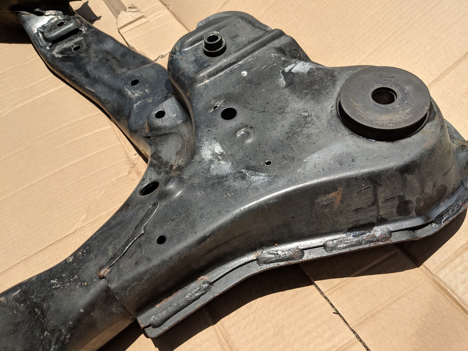
While the car was on the lift I had some covers made on the sub frame to plug the cavitys that were left when the oem gas tank was removed. I felt this was the main source of lift I had experienced when I had the car out that first time. The subframe covers are 1/8 bent sheet aluminum where the other blockoffs were made of of Airmid honeycomb between carbon fiber sheets Dzus fastened on.

Another area that needed attention was the titanium exhaust, it'd been bandaged and slip fit over some mildsteel using hose clamps. It took a bit to source the correct size and thickness Ti piping to match the existing stuff because these sizes were uncommon here in the US. Luckly Chris was able to get exactly what we needed, I requested that he only replace as much as he needed to and leave everything he could from the original system. All in, i think the header back exhaust weighs may 5-6 lbs, Super light and had a very unique 'tingy' sound on high revs that I wanted to preserve.


Next and one of the bigger issues I wanted to handle was the way that the Fuel cell was mounted in the car. The aluminum cell that held the bladder was basically held in by fender washers around m6 allen bolts. I mean- it DID pass tech and some high profile races, but this was absolutely NOT the best way way it could be done. Chris re engineered the mounting box and incorporated some steel straps around the box that that tie into the frame of the car. For future service the front part of the straps can be removed with some m10 hardware and the box slid out.


Originally the car had a pressurized fuel system with a red-head valve that is typically used in Super Taikyu type series in japan. This was removed sometime around 2003 when the car needed to conform to NASA spec rules and the version you see now was the replacement. Below is an old picture of how v1 version looked around 2003 when the car was initially being built. Notice the difference in the fuel cell box mounting between back then and now.

Also gone was the sketchy ass fuel filler neck extension that was on the car. . You can see the old new version vs new-new on the pics below.

Instead of being made out of an old shovel held together by prison shanks the new-new version is a bit more elegant, and much better supported with a larger footprint on the mounting flange that attaches it to the inner trunk.

 |
| Never mind the clear vent tube, that's going to be addressed. |
Another main component that needed some love was the cage. Again when it was built in Japan they did it one way only to have it changed to meet the US spec rules. Below you can see the interesting choice of welding two 45* bars from mid-hoop height to the 'transmission tunnel'. When it got to the states NASA made them cut that out and reweld a cross bar just above the plinths that went straight across to the other side. This is arguably the safer and more common way to do it but it effectively blocked the chassis holes that allowed the car to run an e-brake.

For me, when trailering or towing an e-brake is a pretty mandatory piece of safety equipment. Because of this I settled on a compromise between the two and had the lower bar addition kinked and tied back into the original location. This was the least obtrusive way to fix the cage and still be able to run an emergency brake.

Once that was all done I picked up the car and brought it back to my house so I could take it all apart again.

While the car was away I picked up some TC105N 17x9 wheels from a friend of mine. They are a full inch wider than the Regamasters and I love the way they look on the TSX chassis.
As soon as I got it settled in I had to do a back to back wheel picture before it went up on the jacks.
 |

I have got to say that I really think the new wheels look effing cool. I have another set of 18's that I'm going to try and possibly run, I unfortunately didn't have them on hand when I was snapping these pictures but they are a similar style, just slightly bigger.

Now that the car was home and in the garage for the first time I took a several hours to go through it and document things that I wanted to change-
Shit like this..

and this..

And the wiring... oh god the wiring..


The Pièce de Résistance was wire blob that was wrapped in duct tape and zip tied to the floor behind the drivers seat..

What I ended up doing was going through the looms and any visible connector that didn't plug into something I marked with an 'E', all of these would be verified and removed once I had the looms out of the car. The trick was/is there is apparently no CL7 Euro R shop manual with any pin outs in English. I have found them on some Japanese eBay type sites but normally cost around $380 bucks plus shipping to the states, I feel 'eh' about picking one of those up so I decided to do it the same way i figured out the CRX wiring.. with no manual. I did however buy the TSX manual, but it may as well be for a Corvette as the differences between Euro-R and TSX electronics are so large.

So soon enough I had the dash out of the car and was slowly and methodically marking the looms for dissection.

To gain better access to the bay i'd eventually need to pull the engine out, you can probably imagine how much unnecessary stuff there would be in a car that had been stripped of airbags, ABS and nav- but all of the wiring had been left behind.

Once I had everything out of the car I laid it all out and made sure it all still made sense.

Then came the arduous task of inching my way down the loom and finding nicks, cut wires and overall sketchiness that I needed to fix.
a good example here.
 |
| Before |
 |
| After |
There was also a lot of trying to figure out what or why someone else had done something, like jump these two wires for the secondary 02 sensor only to re-splice it back to the original wires just before the ECU connector. Dafaq?


One of the main things I wanted to check was the pins on all of the fuse boxes. Some plugs and clips took up to 15 min to remove because there was so much sand and grit between the plastics they'd just jam themselves on. An air compressor nozzle and some gentile wiggling ended up being the best method as to not damage any of the pin to wire connections. After I had everything unplugged I went through and cleaned all the surfaces with super fine sandpaper and alcohol swabs I then added a thin coat of dielectric grease and now everything can be plugged in and unhooked without much drama.

To go through the looms I would first need to unwrap the old crusty covers to expose the wires, I'd then trace each individually back to a source and if it ended at a plug with an E on it i'd depin it. I suppose the easy way would be to just cut them and leave them- but I was committed to doing this the hard way. As always.

For anyone who's attempting anything like this, ill teach you a trick. Get a good dental pick and a loose vice. Remove the pin retainer from the plug end (this can be a total PITA on its own). Once the pins are freed from the lock, clamp the individual wires into the vice and with the dental pick pull up the pin finger while pulling up on the plug. After about 50 hours of doing this you become pretty proficient and can usually depin wires with one quick motion and a genital yank. (that's what she said)
 |
| Yellow wire ready for depin. |
This pile represents significant time of unwrapping, tracing, clamping and finally de-pinning.

Once I had the harness getting thinned out I started to plan what I would need to power that didn't have and OEM fuse and circuit already. This work was a bit different from what I had done in the past, i'm trying to maintain things that I would normally just remove and do from scratch. Things like the wiper and headlight switches on the steering stalk along with the OEM ignition with key were left alone because that how they were when the car was built and raced. One may think that doing so would be easier becasue all the work was already done, but I learned that the complexity of having so many wires to trace made a lot of this stuff harder than it was probably worth.
I'll say now - by the time of writing this post I have not started the car.. so who knows, I may have messed something up- I may have messed something up thats so buried in electrical tape and split loom that i'll never ever be able to figure out what it is.. I hope not. But if that's the case V2 will be a scorched earth policy.
One thing that I'd learned on the CRX was to future proof whatever you're doing as much as possible. After some time driving that car I'd gone back and add +12v leads and grounds so i could add things that I had not initially counted on needing. With the Spoon car I've decided I'd build a relay box with significant amount of overhead. Theoretically the hard part would be done- so in the future if I needed any +12/- I could just run a wire to a connector that was already hooked into fused or relayed power.
I started with a sheet of non conductive plastic and built in the pertinent relays and fuses. Layout is important and taking your time to do everything cleanly will save your sanity when it comes time down the road to troubleshoot a problem.


I added the relay board to a waterproof plastic enclosure and ran the cables in approximation of where they'd need to point after mounting. After than I snipped the ends and installed waterproof Deutsch Connectors

Once the box was done I put if off to the side so I could build the rest of the system. Building stuff as individual projects is nice because you can feel like you're 'finishing' things... but can also be a bit disheartening because it can feel like you're always waiting for something else to get finished before you can do another. You just gotta keep plugging away to keep the momentum up.

Now that I was getting farther on the interior of the car I needed to pull the motor out so I could keep the party going of the other side of the firewall.

The same "E" idea was utilized on the motor side of the firewall. I went through all the connectors and traced wires to loose ends where i could.

It's a bit more involved than pulling out a B-series but if you take your time, and think, you can come up with a better way to do it more efficiently the next time.
 |
| motor out |


Flywheel has definitely seen some shit. the bluing on the back is from prolonged hot spots that develop during hard prolonged racing.

Obviously ill be needing a new clutch and flywheel and all new hardware to.

Once the motor was out and the harness removed I dropped the front and rear sub frames, once those were removed I had a chance to start to clean up some stuff here and there.

A little K-mart steam cleaner goes a long way.


 |
| Stitch welds>spotwelds |

 |
| Rear knuckles cleaned/inspected and ready for new bushings |
 |
Everything laid out waiting on parts to arrive.
|
Slowly parts started showing up from Japan (during the down time I was mostly working on the wiring looms) Strangely enough the Spoon Sports racecar didn't have their famous rigid collar sets, I would assume the reason is that the car was built and started campaigning around the world before there was any sort of production parts built for the chassis. Sure, some stuff got put on as time went on- but on stuff like the collars or solid bushings they were just left off all together.


Because everything was already apart, I decided to replace the steering rack bushing and clamp with solid aluminum type bushings. These should considerably change feed back through the wheel and chassis. I cant wait to see how these things change the car on track, this particular kit comes with 4 solid spacer bushings and the rack clamp. I would not try installing these with the sub frame and rack still bolted to the car. Japanese instructions per usual.


 |
| Installed clamp |
Below you can see the sub frame spacers or "rigid-collars". They are a conical shaped bushing made of a specific type of soft aluminum that sits between the sub frame and the chassis. When tightened the sub frame on they slightly deform to fill in the assembly tolerances that are built into the chassis. They are meant to keep the sub frame(s) from shifting under heavy loads seen on track, which let everything stay aligned and doing their job.
 |
| You can see the aluminum edge of the bushing between the chassis and the subframe here |
In the meanwhile I ordered Silicone replacements for all the old cracking OEM hoses.

And while I was at it I replaced the sketchy clear filler tube going to the fuel cell.


As far as the air jacks go- i have still never used them with an actual bottle of nitrogen. Even so- I decided to trace all of the lines to make sure everything still looked good. During inspection I noticed that an AN fitting at the filler wand junction was cracked and would most likely leak under with the high pressure nitrogen.

I replaced the line and fitting and re attached the hose connection to the car. There are kits now days that have these attachment points and disconnects down to a science, this particular kit is not one of those; like everything on this car it seems is a bit dated and used. For the moment the plan is just to repair these types of things and leave it all pretty much original. Later on I may look into replacing the aging air pistons, unfortunatly AP no longer services this model and after looking its pretty much impossible to get rebuild kits. Again, this stuff is good for now but its on a future To-do list.


The airline ingress into the cabin goes just above the fender well on the right hand drivers side.


 |
| New ECU and updated chipset to allow for custom tuning |
 |
| Older more crude technology of the Spoon Sports development ECU |
After getting the suspension out of the car I had been in contact with Ohlins USA about rebuilding and servicing the coilovers. After giving them as much info as I could about them and the car they came back and pretty much said "were not sure what we can do until we see them".. I started to package them up to send them in when I noticed on of the shocks was leaking oil out of the external res hose. 'humm' i thought, 'good thing they are going in for a service..'

About 2 nano seconds later SPLLATTTT, a deluge of pressurized shock oil blasted out all over me, my glasses and everything around a 10ft radius. It took a half an hour to clean everything up and drain the rest of the oil before finishing the packing so it wouldn't soak though the shipping box and spill coilovers out from here to North Carolina.

moving on.

A lot of wiring a car is about smart cable management and learning what order to tackle things in. Back when I was taking apart the car I realized that the older Defi BF gauges just weren't going to cut it. I decided to get something that was near enough the period feel of the car but would give me MUCH more info. I have a Defi Advance ZD system in the NSX and LOVE the way you get all of info in one rather small configurable display. A plus is it only has one 'brain' you need to give power to, you also maintain the ability to daisy-chain gauge readouts and sensors centrally. This was the hot ticket in the mid 2000's, and is still very functional today, but starting to show its age with the uni-color amber display and low resolution. For me, its the perfect middle ground of function and period. The plan is to have the OEM euro-R dash cluster working with speedo, sweeping rev dial and MIL light, but also have this digital version with water temp, oil temp, oil pressure, voltage and fuel pressure along with a configurable shift light
 |
| Defi Advance ZD race set, sensors not pictured. |
Like many things in the car previously, the battery kill master switch and accessory switch were not done the best way. They were mounted to a thin flimsy piece of carbon fiber and in the event of a huge accident or even a violent off track excursion the mounting plate could very likely have cracked and fallen off out of the dash board; which wouldn't be that big of a problem if there weren't exposed 12V battery cables attached to it potentially arcing against whatever it landed on.
I replaced the old plate with a much thicker 3/16 solid carbon sheet and some new mounting brackets. This switch panel would now control main power and ignition kill as well as any of the switches coming from the relay box. The fuel Main & Lift pumps switches have the relay ground fed through an inertial fuel cut off switch for extra safety.

I use screw type terminals and heat shrink the ends to ensure everything stays covered and in place.

You'll see below the inertial switch and secondary brake pressure switch that I am using to trigger the rear brake lights. I de-coupled the oem brake light system so the ECU will still get the brake input signal, but am actually using the pressure switch to activate the rear brake lights. This way I can have the Master-kill switch OFF in the event of something going wrong on track- but still have working lights in the rear telling people i'm stopping/stopped

Below you can see the brain box for the defi gauges mounted in the same location as the BF gauge brain that I removed from the car. In the foreground i'm holding the master kill main cable with the escape ground so if i throw the switch on a running car to kill the ignition I don't back load the system with the spinning alternator and fry my new ECU.

Moving onto the rear I started to build the wire loom for the fuel pumps and brake lights. Building such long legs of wire is ALWAYS a pain in the ass.

Once in the car an wrapped it looks about a zillion time cleaner than the Bag-O-Wires that was here before.

Now coming out of the rear bulkhead, is a nice clean bunch and waterproof connectors. The connector on the left is for the Lift pumps that live inside the bladder, they pick up fuel from the back left and right sides of the bladder and send it to the fuel sump container. I grounded these pumps on the thick steel of the fuel cell mounting stanchion.

On the others side of the trunk is the Main Bosch 044 Pump, the tall container to the left is the fuel sump (what gets filled by the lift pumps) the main pump pulls fuel from here and sends it to the fuel rail, this lets the fuel supply to the injectors be buffered from the fuel slosh that happens in the much larger fuel bladder. You'll see the ground for the main pump goes directly into the frame rail by the pump. Brake light wiring is the bunch of wire at the bottom left of the picture.

All-in-all I removed about 25-30lbs of wires and connectors from the car. That obviously helps weight-wise but was not the only reason for doing this. Having a clean and clear wiring layout goes miles as far as reliability and presentation of a racecar. Lets just hope it all works.

Interior almost finished, layout pretty much locked down and everythings mounted on vibration dampening feet that will also keep the important electronics out of the water in the event of rain.. or a car wash- both pretty unlikely. I remade a passenger side air bag cover plate and also finished the AC vents about the switch plate where the old gauges used to live. Because Racecar.

You'll also notice the re-addition of the e-brake lever and the digital readout on the steering column.

Next I removed the stock shiftier box to re grease the ball and arm. After taking it all apart I realized that the shiftier ball was pretty groved worn, it was totally usable but I found a deal on a billet shiftier arm that i figured that I would try.

This piece is much more sturdy that the plastic and is also adjustable in a few different ways. Once running i'll be able to tune the shift feel with adjustments to throw distance and lateral inputs. Mainly this box will be solid mounted as to get rid of any of the deflection that was in the in the plastic arm and box. This is said to extend the life of your transmission. We'll see.


Not a super huge fan of the look of the shifter in the car but i'm willing to give it a chance, if i don't like the functionality i'll just find a new OEM accord shiftier box.


After much measuring, math, attach/removal and some Dremel work I had everything how I wanted it. The vent tube (the smaller silver one) sits completely flush with the trunk surface and locks the trunk into place when its closed, pretty cool.
 |
| One of the many, MANY test fits. |

I'm still deciding of if I want to leave the wing the raw carbon, or maybe paint it black. I also thought of applying a 'HONDA' sticker painting it back and removing the sticker to reveal the 'HONDA' typeface in negative carbon. That may be cool- it also may be ricey. I cant tell anymore.
Something like in the picture below when it raced in the UK back around 2005ish.

Detail of the filler holes after lines with edge trimming, I had also replaced the rusted and worn out bolts and nyloc nuts that hold the fillers on to make it look a bit less ghetto.

All mounted up and ready for paint.

Now that the suspension and wiring was coming together I had to start in on the engine so I could understand what I had, what i didn't, and what i would need to order.
 |
| ready to come apart |
After pulling things off the motor for inspection my buddy Katman noticed the RBC manifold that was on the car had a pretty sweet crack on the cyl 4 runner.
 |
| How did that happen? |
 |
| Crack from the inside |
I would have normally been bummed but I'd already I bought back my old RSP manifold that I'd used on my old DC5. I saw the same guy I sold it to about 6 years ago at the track one day and asked if he still had it, it was indeed sitting in the same box in his garage since he brought it home. I am pretty happy about that since these are rather hard to find.
 |
| RSP mani on the left RBC mani on the right |

The cool part about the RSP manifold is that it has an increased volume and length runners, whenyou remove the plenum you see it has removable trumpets like an ITB set up inside. This is a REALLY cool design for an OEM piece and will change the power curve on the motor dramatically.

Next thing I knew I needed was a baffled oil pan, I had to search around then wait because Moroso had these back ordered. It finally came and again I was pretty impressed with the quality, if you remember I have one of these on my CRX as well. This one also has extra capacity so you're able to run a bit more oil than the standard pan. Its also a steel piece (which is bad for weight, but good for strength) the stock pan is cast aluminum, so its lighter, but more brittle in the case of any off track excursions- I personally have seen two people lose engines due not realizing they had cracked their oil pan after straddling a curb or going off into the bumpys.


The first thing I did, and the first thing ALL YOU should do, is go through the pan when you first get it with a steel brush. Really get in there and clean off all the micro slag from manufacturing. There are always tiny spherical metal splatters barely held in place. If you were to just swap it on and fill it with oil most of these could work themselves loose and destroy your engine. I also like to go through and use 242 loctite on the baffle bolts to be sure they stay in place.
 |
| micro slag |
 |
| micro slag |
Since I was swapping the pan to the Moroso unit I would also need a new oil pump to account for the oil pump/pick up depth. The z3 style pan was designed to work with the older shorter pick ups that came on earlier k20 motors. My motor is the later model R motor and comes with the RRC pump, that pump has an extra half an inch of depth on the pick up snout. Since i was going to change the pan i'd need to change the pick up to.
On the K-series the snout and pump are integrated together as a unit, which was good for me since I wanted to change the oil pump anyways all i would need to do is buy a whole new unit. I ended up getting a 4-piston racing oil pump. Its ported and WPC treated which lets it flow contentiously at 9000rpm and up to 12000rpm without oil cavitation. The stock pump becomes unreliable when sustained at about 8500 rpm and can introduce air pocks into the oil headed to lubricate the engine. Spending the extra money on these parts can save you a few thousand dollars down the line.

4-piston pump is built out of a factory new Honda unit and comes ready to bolt in like stock. Kinda a no brainer.

In my case I also needed pump chain guide as the one that was on the old RRC pump wouldn't fit the new pump.
 |
| old pump old guide, perfect match. |
 |
| New pump old guide, no Bueno |
 |
| upside down but you can see all the unneeded ports and hoses. |
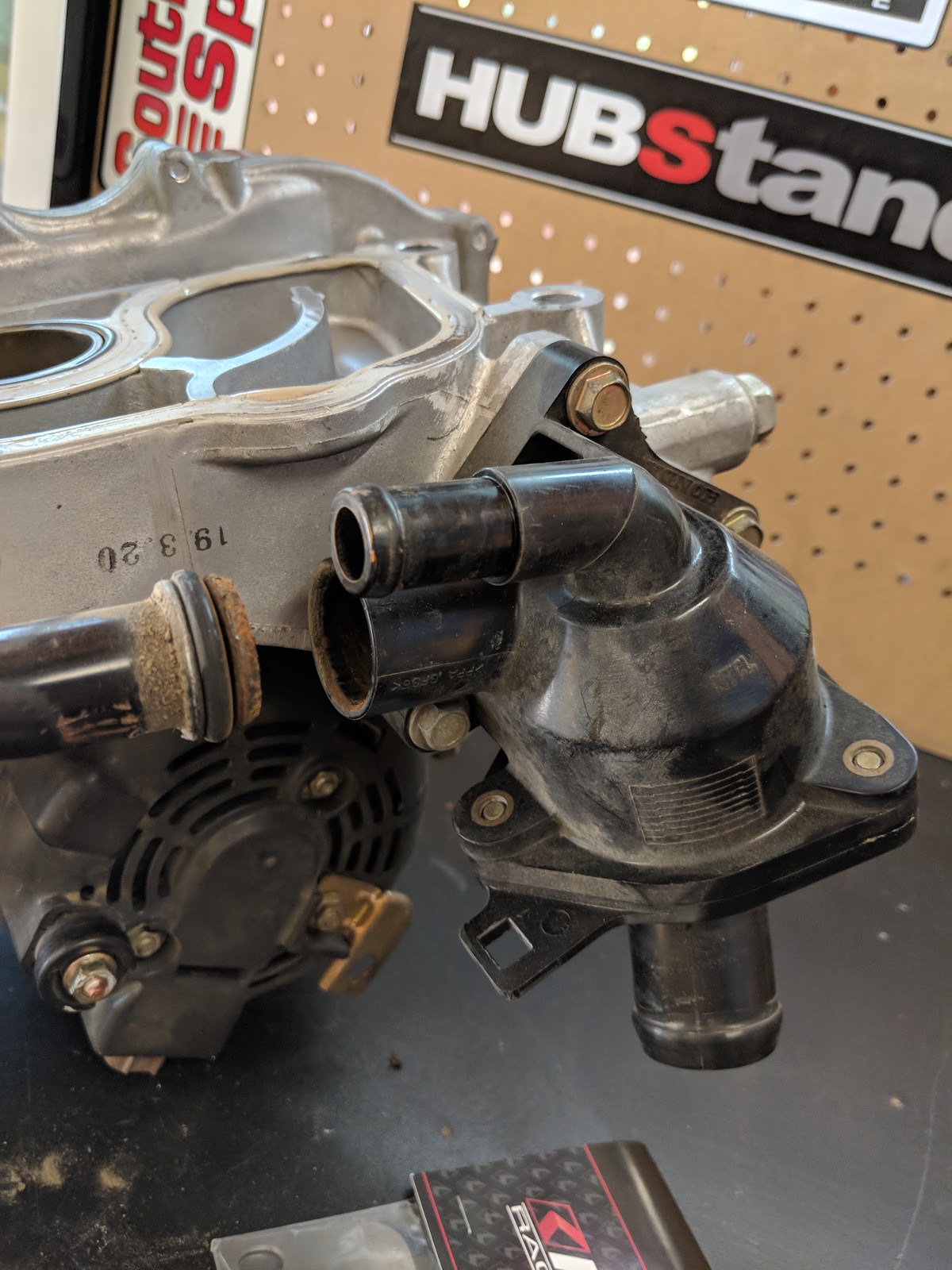
I installed the new water neck assembly and and water bypass adapter. The water neck assembly considerably simplifies the ports coming out of the head and conveniently will allow me to take water temperatures directly from the coolant circulating in the head.

The Water Bypass adapter simplifies the water re-circulation from the T-stat housing to the head. Typically on the RBC and RSP manifolds the hot water is piped through the intake manifold into a provision in the head. This lets the motor 'warm up' faster but on track cars will cause considerable heat soaking in the throttle body and intake runners. Reducing Intake Air Temps lets denser air into the cyls and is a sure fire way to get more power, this helps me do that.
 |
| After some cutting a filing the parts matched up well |
Mating the RSP intake manifold to the Spoon ports throttle body was a bit of a head scratcher, these parts were never meant to be run together and there for took some mix and matching to get the set up working.
 |
| Spoon sports '70' mm ported TB should be a good match with the new manifold |
 |
| The neck down in sizing increases the air velocity into the runners. |
The answer is in a billet TB adapter. I simply filled the spacers cavity half full of JB Weld and let it dry.

Then i woould just need to notch the thin wall between the TB hole and the JB Welded cavity.

This will allow positive pressure to be pulled from the intake pipe, bypass the butterfly and be regulated by the IACV to keep the motor running. New gaskets for both sides and done.
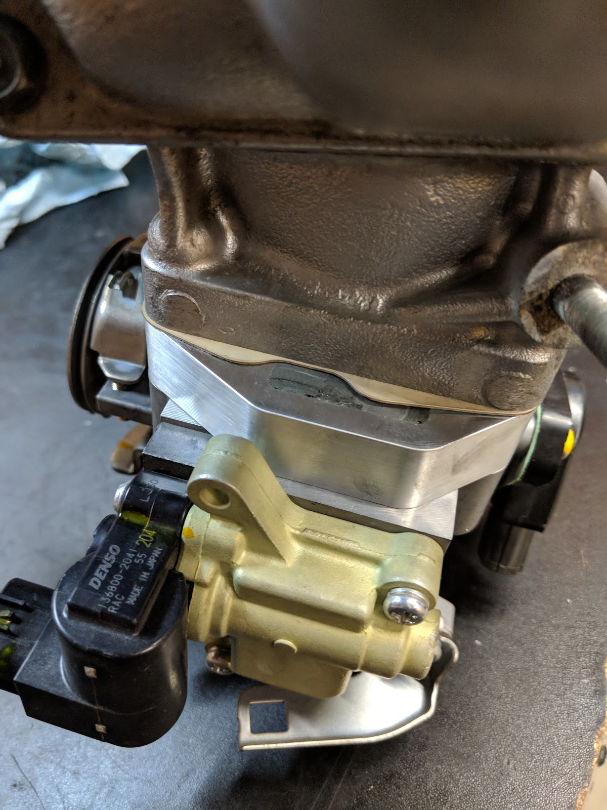 |
| On the spacer you can see the JB weld used to block off the port. |

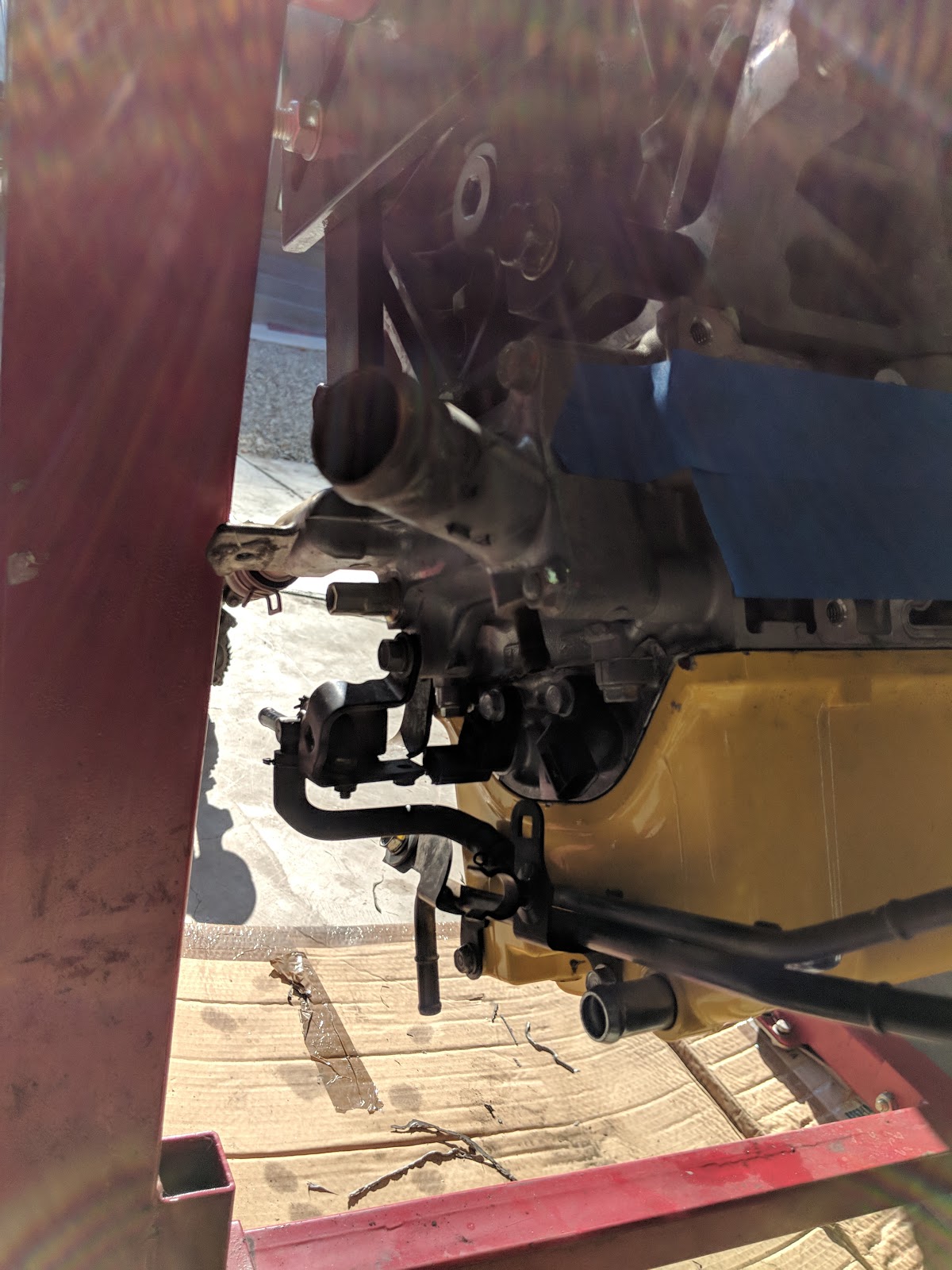
Next was cleaning up the waterlines coming from the T-stat housing. You can see in the picture below that there are 2 main lines coming out. One was the water bypass line that plugs into the intake manifold that we talked about above (pictured here in the stock configuration) and the other line connects to a hardline that goes up and over the transmission and into what would be the heater-core. In my case this hardline had been plugged since new as the heater-core was one of the first things to go when the car was stripped down for racing.

Because it was plugged off I obviously didn't need it, and instead of keeping this extraneous hardline to nowhere I bought a plug kit from K-tuned that removed the hardline all together.
 |
| hardline removed from the T-stat housing. |
And off to the junk box
 |
 |
| Plug and retainer in place. |
More odds and ends showed up to completes some basic maintenance on the motor while it was apart.


I also sent in the injectors for a cleaning and flow test. Glad I did when I saw the pre cleaning test results.
 |
| 2 of the 4 cyls were dripping.. |
I seriously have parts everywhere. I need to start reassembly so I can get all of my work space back.

While waiting on yet more parts to show up I decided to tackle the radiator situation. When I was removing the old one I noticed that aside from being totally filthy and full of sand there were a few gouges in the water matrix that looked like they were only being plugged by the rocks that made them. After sourcing a Spoon Sports radiator I decided that instead of paying the $1900 for a rebranded Mishimoto I would much rather pay the $400 and get a Koyo locally that can be put to the same track abuse and come out the other end. The Koyo radiator is made for the TSX's 2.4l engine happens to be an inch taller than the F-win that it was replacing. Because of the height difference I'd have to make a mounting bracket to re attach the fan and shroud.

I used another piece of super sturdy 3/16" carbon fiber. I measured and slotted it to give the top of the shroud something to 'grab' onto.


I think it turned out pretty good.


After some time I finally got a box from Ohlins. Thankfully it turned out they were able to source the parts needed for a rebuild and recharge. I even had Ohlins put them on their test rig and shock dyno them so I would have some idea of what they were doing.

Once I had collected all the parts for each corner and laid them out I was ready to get everything back on the car.

I'd decided to try some Porterfield R4 race pads up front and run my tried and true r4-S street pads on the back. We'll see how I like this set up, it should be interesting because this car still has vacuum assisted brakes unlike the CRX i'll have to relearn my pedal technique


I used new hardware where I thought necessary and left some bolts loose on this initial assembly for when things need to come apart again to reinstall the axles etc after the motor is back in.

Rear is all back together to.

 |
| The over spray on the rear inner wheel well is bumming me out. I'm going to try and figure out a way to remove that. |
I also ditched the previous hard to access door pull with my tried and true CRX cable type. I'm using an old aviation nylon strap as a door pull so I can still reach and close the door when i'm strapped in the drivers seat.
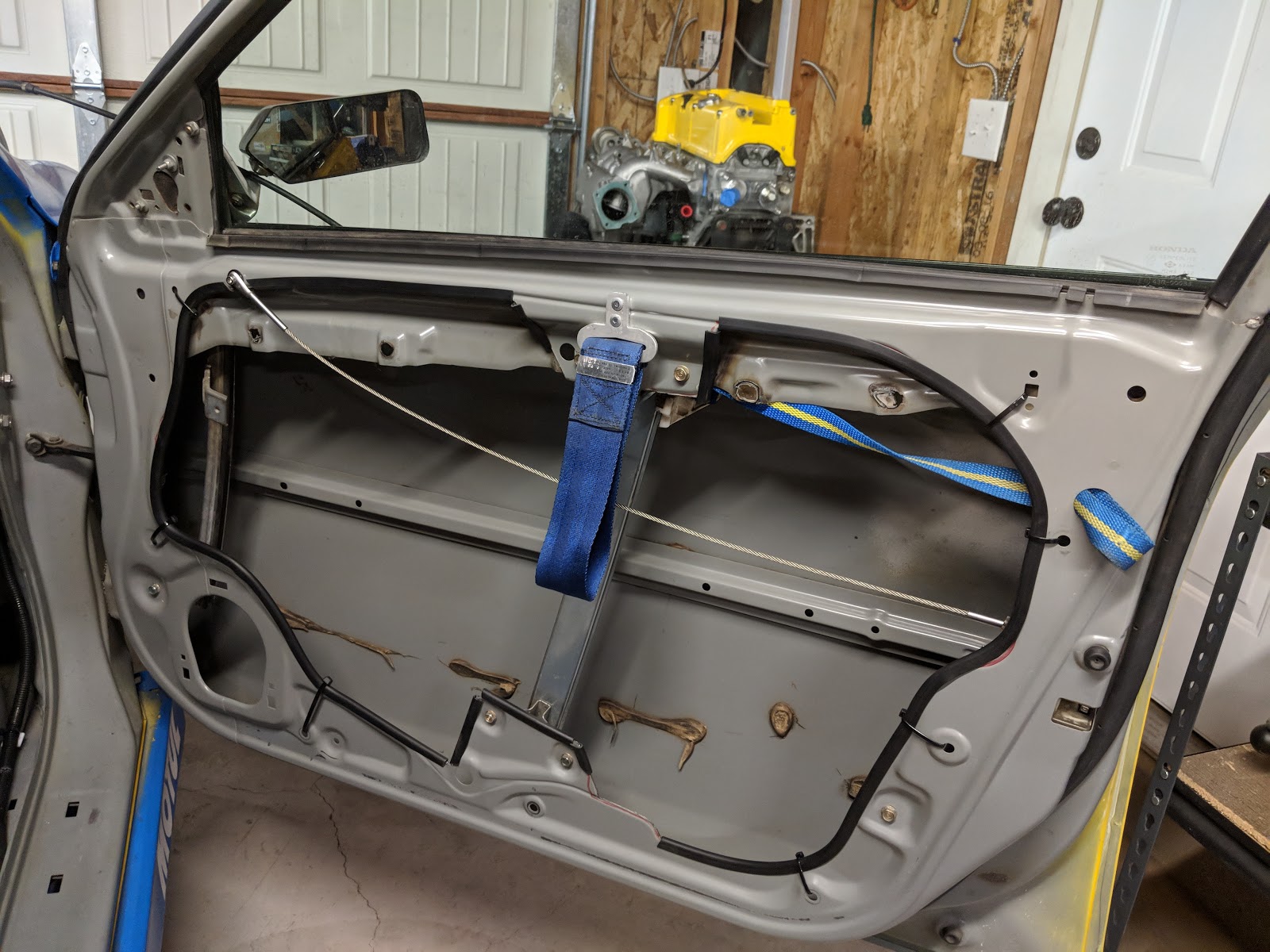 |
| cleaned up the sealant globs after I took this pic. |
I got word back from James on the transmission, looks like it was as beat as the rest of the car... that stands to reason as the K series transmissions are the known weak link.
 |
| never good to see teeth floating around the case. |

Found where all the teeth fit...

Damage on the Spoon Sports 5.0 finial drive..

Mashed syncros..


Looks like i'll basically be rebuilding the entire transmission, which is a bummer. I had James check the plates on the LSD and luckily they were good enough to not need replacement. The transmission is in the works at the moment I'll just need to sort out a new clutch and flywheel and wrap up some finial stuff on the motor before it can go back in. I guess once that happens i'll figure out if i need to re-re-do the wiring harness on start up. Following any sort of dramas along that line I'll be wrapping up some paint and body work and hopefully get this thing back on track for next years HFF challenge.
I'm gunna end this post here, even though there is more to talk about its already WAY to long.
Aside from the odds and ends I didn't get to in this post- I have plans to drop off the CRX and tow-ruck for some fabrication early this coming month. As always, i'll make sure to document the progress for upcoming posts.
I also got ANOTHER car, this one hopefully I wont need to do that much stuff to (yeah right). we'll see..


Until next time!