Wednesday, September 16, 2015

Building an engine harness.


   OK figured I get some of this down.

As I type the car is back off at the fab shop getting the fuel lines bent and some odds and ends welded on; a few weeks late but hey- its a fabrication shop where time is but an illusion.

You'll remember- when I first bought the car and it immediately crapped out on me, it'd forced me to go though and rewire stuff. That time was an exercise in frustration because I had to first deconstruct what the previous owner was trying to do on everything outside the main harness. Basically i had to go though everything and make sure the chassis stuff that I was building and the engine wiring were working together Aside from a few key changes i left the engine wiring pretty much alone. My reasoning was that I knew the main loom had worked at one point so I was limiting my exposure to causing any new problems by not  really changing stuff where I didn't need too.  In the course of doing the v1 rewire i had taken note of where I thought things could be improved and put them aside for later.

Fast forward this far into 'fixing stuff' and add some additional things i've acquired that require me to cut into the 'working-but-not-great' loom. With the reasons mounting I was sufficiently convinced that now would be the "best time" and just do everything from scratch.

   Deciding on a scratch built harness means that I could tailor it specifically to the car. By removing stuff that I didn't need and adjust the lengths i could have a much cleaner fit and finish, and get rid of the stuff that i wasn't really happy about.

  As far as planning this was as big and complex as it can get  Theres a lot of things that one needs in order to do something like this correctly. I took measurements and poured over schematics and diagrams so I could figure out lengths of spools, wire gauge size, current capacity,  wire color, sensor pins, ECU pins, sensor connectors, wire type, wire wrapping, heat shrink type, fuse type. on and on and on The possibility are truly endless, especially if you care to dig any deeper into what makes one wire or plug better than another wire or plug. The truly maddening part is by altering one component- be it wire size splice placement etc; you have potentially out spec'd something else in the system and suddenly created a compatibility issue that you wont see until you're really far along down the garden path. I don't mind saying right off bat that i ordered quite a few things only to find out that they could not be used, or that there was a better option. Its a bummer, its expensive and it is what it is. I'm sure that doing this type of thing day in and day out... or even having done it just once before could have saved time and effort but these things are all part of learning.

As I was eluding too first thing is first

I needed to lock down positioning of the brain so I could accurately gauge lengths between sensors and the ECU. This would let me extrapolate both the ideal wire gauges and lengths that I would need them in.  A good bet is to copy the OEM AWG's- but I had to keep in mind that I was not running any of the main built-in power relays and fused connectors that the car had when it rolled out of the factory, so some some things would need to be changed to accommodate.  ALSO on top of these requirements I was planning to run everything through push/pull fuses and an isolated power switch that could kill the power without frying my ECU. This created some pretty convoluted pathways that I'd need to route currents through at the correct amperage. Some real mental gymnastics.

 Here's a shot of taking measurements off the main bundle.. I had about 30 note pads

Also measurements of the main fan out to the sensors themselves. I hate rats-nest wiring and wanted everything to be a tight and simple as I could get it.


  To make matter even more complicated I also decided to run a CPR Coil-on-plug ignition system. This meant that I would need to wire the CPR controller box to the ECU and have the correct signals go out to the spark plugs. The kit shows up as a premade plug-and-play harness thats meant to run along side to the main vehicle harness. This is good for 99% of the customers but since I  had everything apart I figured I would route it all through the main  loom to. It would also give me a chance to clean up the lengths and give it some better heat shrink and wire join protection. I found I could also simplify that harness even more since I was already running a non OEM set up.

Cut the ends of the brand new Hondata harness..

wire tape? really guys? Here's a the electromagnetic interference toroid tube that I would reuse in the new loom.

Old engine harness at the top and the COP conversion harness stripped at the bottom.


After figuring out lengths, wire gauge and the best way to route the correct amps, I'd had to tool up so I could actually build it.  I can say that this was the most frustrating part of the whole ordeal. I figured that all the information needed on what types of electrical connectors and pins that mate with the sensors would be somewhere on the web...

   Not exactly. I knew that they had to be SOMEWHERE- but I got zero help from the dealership and basically nothing form any online forum. The people who did know (companies that make aftermarket harnesses for a fee) pretty much refused to share any information. Since I had decided on doing all this right, reusing connector pins by prying them off the old wires was not an option.  Solderless Molex pins weaken considerably after the tabs have been crimped once. Prying them up then back down on a new wire is asking for intermittent electrical problems caused by loose or weak connections. 

This is not alchemy and i don't believe in hoarding information- so i've decided to share what I collected during HOURS of calls and research in the hopes that it helps someone that is in a similar position. 

Heres the pin connector dimensions on a b18c1 3 wire plug that have the water stopper

And here is the pin dimensions of the two wire plugs 


the plugs are made by Sumitomo and are the HW series. These car be pulled outta the junkyard and reused.. or bought new. 

Get them here
-http://www.corsa-technic.com/item.php?item_id=226
-http://www.corsa-technic.com/item.php?item_id=255
-http://www.corsa-technic.com/item.php?item_id=521

This is the Molex crimper for a 2.9mm crimp, it has provisions to crimp the water seals too (3.2mm), most don't.

-Molex 63811-1000 Service Grade Hand Crimping Tool-- amazon has best prices.

For the injector clips get these, they're WAY better that the shitty obd1 Honda ones and these come with pins. You will need to heat shrink the back so they are water tight though. 

http://www.xenocron.com/obd1-injector-clips-pins-p-166.html

For ECU pins get these-
http://www.hamotorsports.com/obd1-small-pins.html


and these:
http://www.hamotorsports.com/obd1-large-pins.html

For the Hondata CPR harness wire end pins that connect to the CPR box the part number of the connector pins are

1-170291-1


Some of this stuff has minimum orders, you can get lucky and find a place that dosen't if you look. For example, I needed 4 of these...

so yeah.

For the other stuff grab from the junk yard if you can. Its always good to have extras as you can damage clips or ream out holes when taking these things apart. A few extra bucks at the check out can save you the hassle of a whole'nother trip back

Junk yard run...


Here's a good point to say: To do this yourself is NOT cost effective if you have to tool up. Sure there is an argument that you will retain the tools to use again in the future- But honestly, how many people are going to do this more than once? I, personally, like to have tools and experience; even if only to find that i never want to do this again, that is 'worth it' to me. (for example i have a automotive paint sprayer and compressor but will NEVER paint another car as long as i live, but i can) 

 If you don't care about that- just get a new harness from one of the companies that offer them. It WILL be cheaper and easier in the long run. 

If not be prepared to spend

-300 on tools, crimpers, strippers, heaters etc
-100+ on good wires
-250 on good heat shrink and butt connectors
-100 on pin connectors
-100 on misc
-100+ on shipping for above
 Time, so much time.

compare this to the cost of a custom built milspec harness delivered to your door. There you go. 


Now that I had my parts and measurements and parts i got to work. 


This is one half of my 'working box' it keeps everything as organized as possible, which is essential when working with such small parts. A lot of these thing look similar but are incomparable with one another, double and triple check the connector your about to crimp. After about 10 hours I was finding my focus falling apart and I was just about to make some pretty bone headed mistakes.

In the box you can see Deutsche connectors. I'm using a mix of DT and DTM series connectors for power and ground. I'm building them into the system so they it can all be moved around as a unit and able to be quickly disconnected and serviced. More on them as I start to wire the chassis.

  For wire i'm using aviation spec tin plated copper multi stranded wire. 16/12/10 awg for respective lengths and amp ratings. This wire is MIL-SPEC aircraft grade and has PVC coating that wont give off toxic fumes if burned. 

    All the wire splices are heat shrink butt connected, ratchet clamped, then heat shrunk with Raychem es2000 adhesive lined heat shrink. This binds the wires together with a glue that prevents corrosion and greatly increase the pull-apart strength of the splice. This technique will be used throughout the car where wire splices are necessary, but especially inside the harness where service will be impossible.  The wrap sleeve you see peeking in is a product called Insultherm. Its a non-fraying resin coated fiberglass sleeve that is watertight and can withstand heats up to 1200 degrees Fahrenheit. Its also made in California, which is cool.
The downside is its a non shrinking sleeve which makes getting the diameter size for the loom your building a little more difficult. I decided to wrap the wire bundles together with 2:1 polyfin shrink to create crisp bundles that then feed those through the insultherm sleeve. The ends of the insultherm are held in place with ES2000 adhesive shrink as above in the splices. Its probably very overkill but i hate dealing with brittle wires and shitty plastic heat shrink that cracks.

Below, you can see the soft silicone plugs that will slip into the back of the sensor plugs to keep the water out. I MAY go a step further and use the resintech R250 goop to seal the back of the plugs, i'll do this only after the harness had been thoroughly tested.   


Measuring the strip ends is important. you want the gripper fingers to grab onto the PVC insulation firmly. I ended up stripping the finer wires with a razor blade by hand. Its time consuming but ensures you don't gut strands out of the wire and compromise the connections.

These have been crimped and are water tight when slid into the plug receptacle


Its all about building it in steps and not too rush. Heat shrinking is fun but only to be done at the very LAST step. It helped to think of each ECU plug as a stand-alone where I would only work on that plug until all the lengths to the sensors were complete. Id then Ohm test the connector ends to the plug port to make sure I KNEW where the wire was going- then id go have a test fit on the car. Only after everything was confirmed I would strip and clamp the pin ends on. Only after all that was done would i shrink the sleeves down. Last step was connecting the connector ends.

Here you can see me testing fitting the lengths of the injector leads before crimping the pin ends. Doing these dry installs frequently was time consuming and probably not the best for my lower back but it let me dial thing exactly how I wanted them.

I have mounted the ECU onto a rally car foot pad, Its isolated from vibration by 4 1" threaded fuel safe rubber risers. This insures that if the floor gets wet from a leak or rain the ECU will stay up out of the water and safe. (same is done with all the +12v sources)  You can sees Deutsche BUS plugs on the left. these will feed power to the saturated injectors and IACV these are direct 12v that are on a 20 amp beaker the injectors themselves are controlled by a grounding signal from the ECU so the power and amps they require to function are very small in comparison to peak/hold types found on other cars. The black plug side will act as a chassis ground for gauges and the ECM. The majority of grounds for the engine sensors themselves need to be grounded through the provisions in the ECU's circuit board as they have a built-in defeats for grounding feedback. The sensors on the motor CANNOT be grounded to the chassis.    

Harness coming along, added injector pins and ready to seal them watertight to the insultherm.

Depinning the connector on the CPR was a HUGE pain in the ass and took about an hour and a half by itself to do.

Figured out a system to depin the plugs while using the probeat the same time.


For the crank cam and TDC sensors I used 4 signal shielded wire with 24 gauge leads doubled up. I grounded the shielding wire and metal wrapper to a 16awg wire and adhesive shrunk it all together. The black wire to the left out the back of the heat wrap will be grounded at the Deutsche grounding bus terminal. This will bleed off any EMF interference that the magnetic sensors see and give the ECU a more accurate reading.


 Here is the harness getting closer to completion. In this pic the Coil-on-plug CPR harness had been integrated and the starter button leads and ignition signal to the coils had been isolated. This was a necessity so I could run it to my new tandem kill switch. (more on that later)

In all this took about 6 pains taking days to complete.

One of the final test fits. You can see how much cleaner and professional the harness is starting too look. 


Inside shot during the same verification. You can see all the extra leads that would be used for starter and power hanging to the left. The CPR box is mounted near the ecu by vibration resistant pads where it will be hooked up to the wires hanging off to the right.

Here's the carbon fiber sheet that i cut to use as the harness pass-through on the fire wall. It will be riveted on the fire wall in place- The 1/4" gap all around is intentional to accommodate a silicone doughnut gasket. This will be water tight after final installation.


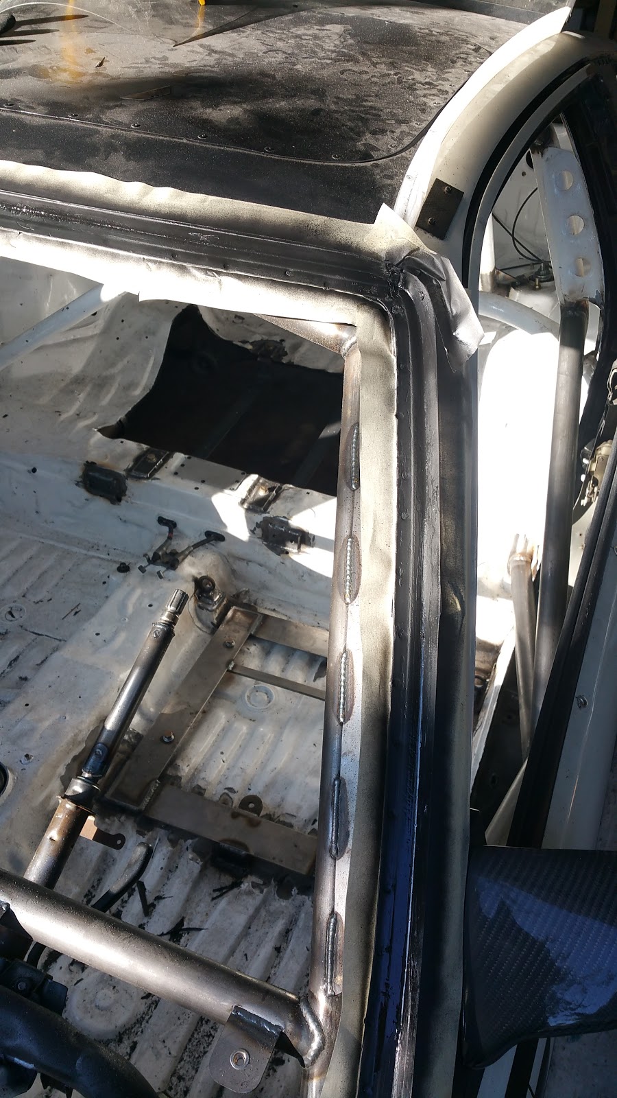
sideways shot of the routing (upper right is the distributor) the harness is tucked neatly into a slot near the starter.

Now that I wont be using the dizzy anymore I bought a cool billet block off piece from LoCash racing. I also blocked off the vtec oil pressure plug since I removed that from the harness.

In the pic below i'd Starting to wire in the power to the Deutsche connectors from the harness to the chassis side.

 I have some cool things planned for this and can't wait to get the gauges and everything else in here. the addition of those will really make it start too feel like the car is actually coming together...   As for the wiring harness itsself, its done, as in- all heat shrunk tight.   To change anything now would basically be a total do over, and knowing how much work this took it makes me really anxious to fire the car up. I mean, nothing was left untouched so there is A LOT of room for error. Once the fuel system is done I can plug it all in and test. That will be a big moment when it comes.


For now the car is back to the welders for fuel lines and final odds and ends.


In the meanwhile Ive been buying more parts--- and also got this:


All aluminum featherlite 3110 trailer, FINALLY. I unceremoniously sold the ae86 which cleared up the room. Out with the old in with the new. Hopefully i'll have the crx sitting on top of that bad boy on the way to the track within a couple months from now. We shall see. 


Until the next time.

Friday, September 4, 2015

Almost ready, again.....


Alrighty then..   Figured id try and get an update in even though I'm still in the middle of a bunch of things on the car.  I've been doing so much I know i'm going to start forgetting details and would rather put stuff here as its fresh. I try and refrain from posting about stuff that's 'in progress' in case I end up changing it mid course (which is not uncommon) but im going to hit every thing I can think of and maybe go back and edit once they finish.


I have been doing research onto intake systems on B series race motors. One thing they all seem to have in common is they use an "induction box" around the intake. Ram air collects in the box at  higher-than-static pressure and therefore is instantly sucked/expands down the throttle body as the butterfly cracks open. The engineers are taking advantage of an atmospheres almost instant ability to equalize pressure. Since the air isn't just being vacuumed down intake pipe by the stroke of the piston you get a sharper, more instant throttle response. This of course varies with speed re: the pressure built up in the box- but I am curious to run some of my own 'butt' testing.

To accommodate this I built a 8x4x6 deep bumper duct and terminates into a 3" smooth mandrel tube that will do a 90* up into the bay. the box will be sealed off air tight, which is essential to maintain a higher pressure than ambient, this box will be built around the biggest filter I can find that will fit in the space, the more filter surface the more instant the air can move.

Here's a picture of the bumper ducting. I used the provision for the OEM turn signals and had to have the bumper beam trimmed at the ends since my 3" air pipe wouldn't fit through the hole in the sheet metal of the support. This has taken quite a bit of thought since I would still like the bumper to be removable in seconds i've devised a way to build a light simple disconnect interface between the ducting and the charge tube, now i just have to get it all together. I have a few of the parts done but no pictures to show as of yet.


 I made a quick carbon plate to block off the turn signal on the other side to match. The lights that used to be here never had working wiring so its nice to get rid of the haggard looking cracked plastics.

Once the car went off to fab all was quiet for a couple weeks while it was pushed around the shop and SMP finished up other projects. Once they dug into my car progress started coming fast.

Some shots of the cage taking shape. Upper halo cross bar. Not necessary in the rule books but something i decided on anyways. You can see the intersection angle that was necessary where the main hoop and halo meet. this was mid progress before it was reinforced.


Since I was no longer going to run any dashboard I could have the cross bar put in its place. This will now serve as the back bone of the instrument cluster and switches. Its nice to have something substantial to mount things too instead of the flimsy plastic dashboard. . I kept the OEM steering wheel bracket since the pedals and steering column are all tied into it. I'll maybe think about removing it at some point-- but it'll require quite a bit of things that id rather not deal with like  aftermarket pedal set and re routing master cyls. So far its fine, I was able to lower the column with some studs and some spacers to account for my new seating position farther back and its holding firm. I also like to have the tilt feature so i can move it up and down to work under the dash and get in and out of the car. Again unless I come up with a good reason to take it out it'll stay where it is.

Here is a good side shot where you can see how the door bars angle out and joint at a point in the center of the door. The foot plate has an angle and is welded to the door rocker and the floor.


To accommodate me sitting farther back the switch panel legs were moved up about 8 inches so I could more easly reach battery master switch while fully buckled in.


Below, you can see the seat bracket permanently welded into the floor, much stronger than the OEM floor spot welds and it gained me about 3 inches of head room to clear the top bar with my helmet on. This has also allowed me to sit farther back almost dead center between the front and read axles of the car. You can see peaking up in the top of the picture I ditched the shitty NRG disconnect and spline adapter that the car came with and installed my Sparco weld on disconnect. This is a HEAFTY part and is the used on Ford and Subaru WRC cars as well as other series' touring cars . The length of the steering column was extended and a tube sheath created so it could be welded around the edges and then butt welded though holes drilled into the tube directly to the shaft. This. is .going. nowhere. Now I can have the steering wheel sit closer to me and a better angle = more control. You can also see a plate in the backgroung was built to hold the battery and SPA EFF fire bottle. More on these later. 


Here you can see the filler neck mounting, i felt the angle of the fill pipe would have been too shallow of an angle to run from the OEM location.  Also there wasn't a good way to beef up the stock fuel mounting point for the fill neck which would need some strength To support any weight of fuel left in the neck after a refill. The filler cup It has a built in drain dump port that i am routing off back under the car away from hot components in case of an over fill. On the cage you can see a diagonal cross bar has been added to the rear 90's style square cage down bars.

Also been gusseted to the shock tower for added support.

I had Steve add an anti-intrusion bar for the foot well (those two nuts hold the footrest) In a bad accident I have seen wheels come into the cabin area and brake ankles. This bar will stop that from happening.


Once I got the car home I test fit everything again and took measurements and made lists for things that I would have to start to figure out, like wiring and brake and fuel lines. These tasks  come with piles and piles of list of things that I would need to buy.
You can see here the dash layout with the shift and emergency light being the most front and center. If its not buzzing or flashing at me it means its within spec and I don't care about it at the moment. The space in the center of the between then orange red and blue light is for the laptimer. Because, you know, that IS important.

The fuel cell (the original reason for tearing apart the car to make crx v3)  had its provisions welded into the car too keep it everything in place. After i brought the car home I did a quick mock up and took measurements, its nice too start too see everything coming together (even though at this point there is a LONG way to go)

You can see in better detail here thick reinforced steel pads had been welded into the chassis and cage, the bottom is held by thick steel straps running lengthwise in the OEM location,  the top is secured by two thick straps coming from mounting points on the cage down to pads and bungs welded into the step area of the back seat. the top is redundantly held down by 40 or so 1/4 inch hardened black oxide screws and lock nuts, 4 of which pass through the top straps. 

Pic here of the bottom, aerospace gold foil added to the outer can to deflect up to 85% of radiant heat from the exhaust. There is also a layer of closed cell non crush foam between the bladder and the aluminum wall. The gold foil was probably over kill but it sure looks cool.
You can see where I had started to seal the aluminum box in place with chassis sealer. Its waterproof, fire proof and semi flexible but also hardens into a rubber like stiffness to seal up the inside from the outside. For whatever reason I have built this car to be water tight and spent extra time sealing up holes and figuring out solutions to closing gaps, which is a bit funny because the car will never have windows on while racing on track.


As I was cleaning up the windshield gutter I noticed that it was a bit rusty. Nothing that would be a problem but I took the time to take care of it correctly anyways. 


3 coats of rust-stopper gel. after scraping off all the old windshield sealant.

5 coats rust-stopper gel.

Then a quick mask and spray with zinc based rust inhibitor paint

After cleaning off all the metal dust from the fab shop and wire wheeling the slag spatter from around the welds I masked the car and gave all the new metal a fresh coat of epoxy.


Looking at running the stock trunk popper i'd decided to lose the rear hatch mechanism all together and replace it with some toggle latches that my friend Dave had given me from his Alfa restoration project. I knew already that the car would never be parked outside and these toggle latches added an element of safety for someone outside the car being able to get in the car if they needed too. 

You can see the well cell bladder that would soon be in the containment box, the surge tank is at the bottom and the fuel feed and return lines are hanging out the top. I'm using this box as a leftover from the initial phases of the ae86 build.  I had thought about getting another bladder but why spend a grand when I already have something that will work.  I did however replace the stock fill plate with a fancy-smanchy gold aluminum-alloy one-- I think i talked about earlier in the blog.

After plumbing the lines and securing everything in the containment box my buddy Allen and I tq'ed down the zillion small screws.

Once it was all together we CAREFULLY positioned it into place in its box. You can see here I had already sealed the chassis to box gap and painted it. it looks pretty seamless and pro.

From the backside. 

Not much too see here, but that's the point. I filled all the small holes in the floor with goop. I'd go back through later and clean up the excess when it has semi dried. 

 Painted my steering column. You can see that I'd also drilled out and removed the steering lock and ignition tumbler, which is in the SCCA and NASA rule book.


I needed a solution to the missing door frame since I no longer had a place to put a door opener. I found these aviation chords with integrated clevis at a parts surplus store and they looked like they'd do the trick.

 I was right, they were the perfect size- I used a nylon slippery washer on both sides of the clevis and a nylock nut to hold everything together with the slightest amount of free play. You can push down on any part of the cord and the door mechanism will actuate opening lever. This is a perfect solution for use with racing gloves or of you are in a hurry to get out.

You can see the OEM crash bar is still on the door, at this point they're just dead weight. I spaced on having them removed when it was at the fab shop the first time,  I'm going to remove them from both doors as they apparently weigh 30lbs a piece


Next up was starting to plumb the stainless steel hard fuel lines. Id been a bit nervous about tackling this as the work will come out as good as the tools your using will let it. You can see here i fire sealed the fuel pump and filter box earlier too.  I measures and drilled holes for the hardlines to enter the box, this took quite a bit of math and time to get right.

After drilling the holes in the right spot I bent a piece of test wire with my hand held tube bender in the shape and path that I wanted. This stuff is not easy since you are working on 3 dimensional planes of X,Y and Z you have to be dead on on the lengths of the tube that you are planning to use. You need to take into account the radii of the bends eating up tube length. kinda a pain. 

Here is the finished product of ONE of the fuel lines that is bent into place. 


After cleaning the cut with a deburing bit and trying to flair the captive nut onto the tube I realized pretty quick it wasn't happening.  The tools I had bought were not up to the task. Turns out they were spec'd for much softer aluminum tube and this stainless was just slipping through the holder as I was cranking down the fairing cone. After a bit of research into how much the correct 37* hydraulic flaring tool would cost it started to become clear id save quite a bit of cash by putting this on a list for SMP to do when the car goes back in. 


Moving on to the next item I decided to rust blast the drivers side quarter window and install carbon where the glass used to be. I repeated the steps Id done on the windshield.

After cutting and shaping a carbon square I riveted it into place. This wont be a blind-spot since I could never see out of this window while in the HANS seat anyways. Painted and again I weather sealed all the seams to insure this was watertight.

Once the carbon replacement window was in place and I could finalize the fill tube and its connection with the fuel cell.
I bought Coast guard approved fuel filler tube. Its got stainless steel coil wound around a rigid  kevlar skin and 4000lb burst pressure rating.  Its puncture proof up to 22 caliber and you need a heavy duty chop saw to cut it. I wrestled with this for longer than id like to admit but finally had everything in the correct angle and all clamped down with 1 inch wide bolt clamps. 


I mocked everything up again so I could start to brainstorm the best and most clean way to wire everything.

After getting my head around where to start I turned to my hacked circuit board builder program and made rough schematics so I could come up with a list of connectors, fuses, buses and wires lengths/gauges id need to buy.

My next step is to figure out lengths and layout for the essential components that I will have to account for in the new layout.

More labeling and measurements are taken and much more research was to be done.


Again, the majority of the time was spent figuring out what the PO had had done to the harness. I had every intention of turning it back to stock layout with removed unessential connectors and wires but before doing so i had to understand why he'd gone and done certain things

Like this...

To make it just that much more complicated I had decided to run a coil-on-plug set up. I would no longer be using a wasted spark distributor so ide be able to gut the internal coil ignitor and rotor. This meant that I had to make sure that requisite wires and signals were in place so I could incorporate the new hardware.


Test fitting the coils on the motor... the ugly wire sheathing will be gone and integrated into the harness im building from scratch

I did notice that i may have clearance issues with the s2000 coils i'm using. The hood is already touching the valve cover and these are sticking up past that. I'm looking into different options for this, sorta on the back burner for now,

In preparation for building a harness from scratch I bought many many wounds of military aviation spec wire, tools, crimpers, connectors, connector pins, cable saddles, pins, heat shrink, fabric shrink, relays, deutsch connectors and shielded wire. All in all I have spent more on just tooling up to build something myself that to just buy an off the shelf mil spec harness. 

Junk yard run for any connectors that I couldn't find.  new old stock or new off brand are next to impossible to stupid expensive. I grabbed all the oem ones i could find so I have spares.

A big change to the driver/car interface layout is i've decided to use military spec circuit breakers in place of rocker switches. These are push/pull type which means they can be used as a switch on circuits as needed; or simply left in 'contact state' to power up items when I flip 'on' the master battery breaker. I've also invested in a better master switch to be able to accommodate power delivery to them as well as and alternator surges when shutting the car down. A bonus of using these breakers is things like fuel pump and ignition circuits can be reengaged on the spot if they are to blow.  So instead of having to get a tow off and ruining the session for everyone else i can simply push them back in to reengage current flow and get off the track under my own steam. Much more on this as i get into the wiring post next.


 Pretty cool catch can drain solution I came up with both cans drain into a Y pipe and stop at a petcock (off of a YZR race bike) the petcock is riveted into place solidly this allows for me to drain or check the blow-by accumulation without having to remove a bunch of parts.

Lastly for this post I cut and shaped aluminum plates and riveted them on with watertight sealant to the wiper cavity. It cleans up the lower windshield considerably


Next time- on to the wiring...